BTEC Level 3 Games Design
Unit 66 - P3 Creating a human model in Maya
By Dave Johnson
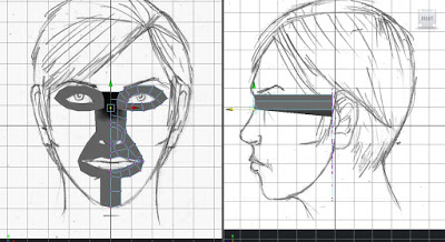
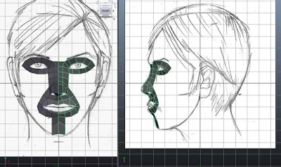
I have described my process for creating and rigging bipedal 3D models below. The first thing you will need to do is create 2 reference images for the front and side of the head. The two below are ones I created, but feel free to use them. For each, insert a plane polygon, then right click the shape with the mouse. Choose:
Assign new material.
Lambert.
In Common Material Attributes Panel, click the checkered box next to Colour.
Click File.
In File Attributes Panel, click the folder next to Image Name.
Navigate to your image and click OK.
It should appear on the plane.
In Channel Box click Rotate X 90 degrees and / or Rotate Y 90 degrees depending on whether you are setting up your front or side view.
Repeat for the other image .
Line both up with the grid so the grid centre line is down the centre of each image.
Pull both of the grid like this:
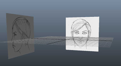
Select both by shift clicking them, then in the layers panel, right of screen, click the 'Create a new layer and assign selected objects' icon. It's the fourth one along, furthest right.
Next to the layer name that has been created there will be a blank check box. Keep clicking it until 'R' appears. This means the images are for reference and cannot be selected by accident
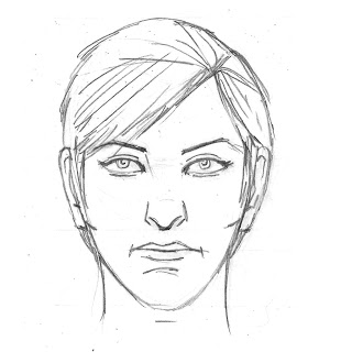
Front View
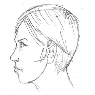
Side view
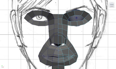
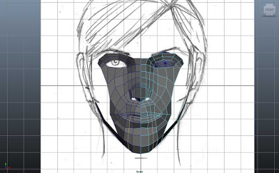
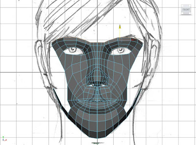
1) Begin by clicking the 'Create Polygon Tool' under the 'Mesh' and draw around one eye in your front view port. Extrude out the edges of this and delete the face that is covering the eye. Extrude the two edges nearest to the bridge of the nose and pull them to the centre of your grid. After this go to the Duplicate Special menu (click the little square to the right of the option) in the Edit drop down. You should be presented with something similar to this dialogue box:
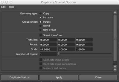
Set it up exactly like this, with geometry type instance and x scale -1. Click Duplicate Special. This will create a reverse mirror image copy of what you have just done. The beauty of it is all changes and edits you make on one side will also appear on the other. Perfect for modelling a symmetrical face!
You should end up with something like the image 1), so continue to extrude edges downward to cover the nose. Just block stuff in for now, don't worry too much about detail.
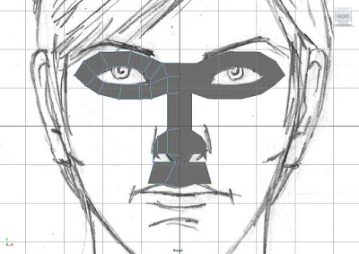
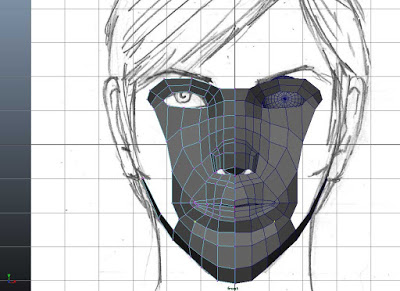
2) Continue blocking in the area above the top lip by extruding edges, just as we have been doing so far. Follow the exact pattern of the mesh in the picture if you can.
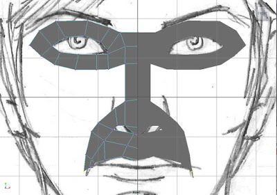
3) Continue to extrude the muscles downward and around the mouth, and begin to create the shape of the mouth itself.
4) You should end up with something that looks like the picture above.

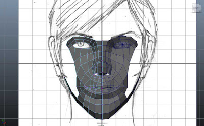
5) Continue onto the chin. Again, just block it in for now, don't worry about the detail or curvature of it.
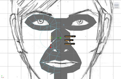
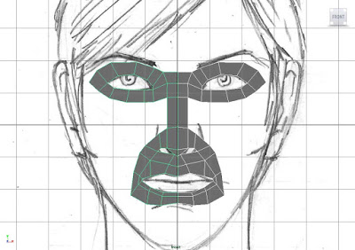
6) Now take the edges of the nose and extrude them out. As much as possible you'll want 4 sided shapes, or quads making up each part of your mesh. 5 sided are ok sometimes and even 3, but don't go above 5 sides. If you right click on your object you'll have the option to select vertices. Do this, and select any two vertices you want to merge together. In the case of the image above, you can see that I have extruded out an edge and now want to make it part of the existing mesh by merging vertices. I would do that like this:
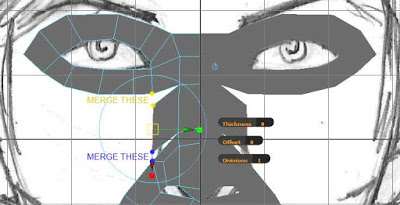
You can see I have two vertices in yellow and two in blue. I would select both yellow and click Edit Mesh > Merge. The same for blue. Once in a while, it helps to select every single vertex and just click Edit Mesh > Merge. This makes sure that each half of the image is stitched together by it's corresponding vertices right down the centre. Not doing this will have some weird effects later on, as the computer will think it's got two separate objects and will struggle to understand they are supposed to be joined together.
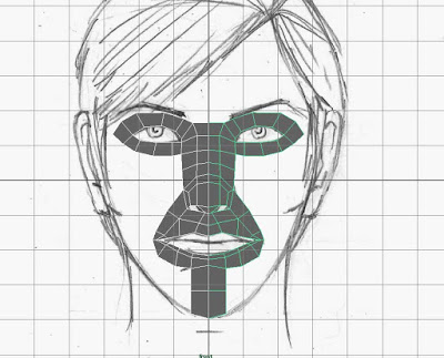
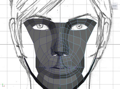
7) You should end up with an image like the one above
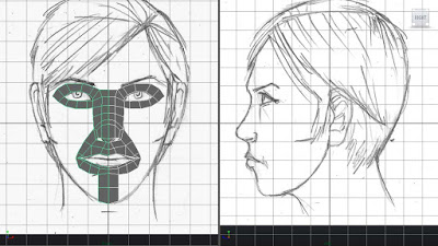
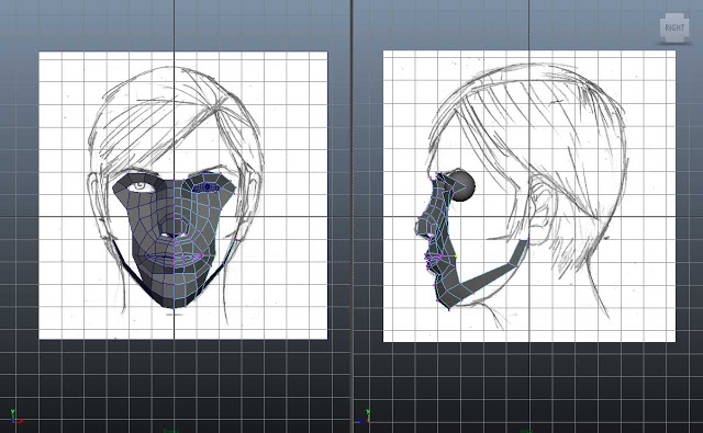
8) Now let's get that side view involved! Set up your viewports so you have just the front and side on screen. You can do this by going to the 4 port view and pulling the dividing line that runs across the screen centre upwards.
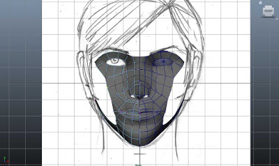
9) Begin the next part by concentrating on the centre most line of vertices that runs from the bridge of the nose to the chin. Choose the one that begins at the top centre of the face (bridge of nose) and pull it in the side view so it matches the profile of the drawing.
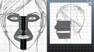
10) Continue onwards with that centre line of vertices and you should get something like this by the time you get to the chin.
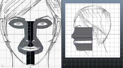
11) A quick word of advice on the chin. At this stage they are the only vertex that you can pull up and down, to match your profile (see image above). All others, just pull them left and right. You may feel restricted by this and think your image isn't working, but trust me, patience is worth it eventually.

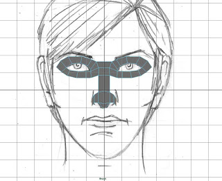
12) Continue onto the next line of vertices out. If you are unsure, look at the coloured chart below, after the central yellow vertices, it shows which group you should work on next. I work inwards to outwards - yellow, then orange, then red (only two of these), them magenta, blue, cyan, green, black, brown.
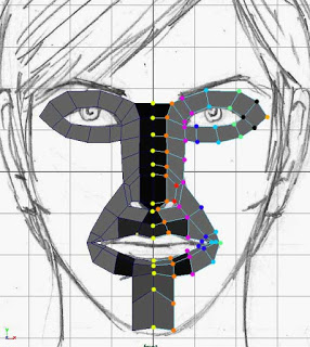
REMEMBER - WITH EXCEPTION OF THE CHIN, ONLY PULL VERTICES LEFT AND RIGHT.
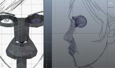
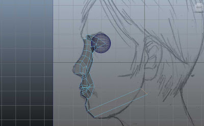
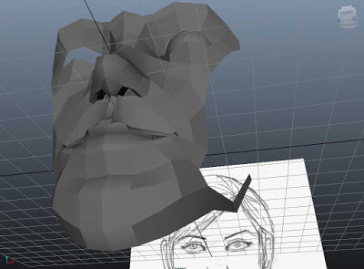
13) Following the contours and lines of your drawing, you should end up with something like the image above. Notice how the eye socket has begun to shape itself. To get it looking just right, let's drop in a polygon sphere for the eyeball.

14) In front view select the sphere, size it accordingly and hold J whilst rotating it. This is so we can use the polygon pattern in the sphere to give us a good idea of where the pupil would be.

15) In side view move it into place.
16) In perspective view, take the vertices around the eyeball and move them forward or back to follow the curvature of the ball. You want it so that no part of the eyeball can be seen OUTSIDE the face - we want it to sit snuggly inside.

17) In front view tweak the same vertices so they look good and cover the eyeball. Now we are going to work on the lips and mouth. Take all the edges around the inside of the mouth and extrude them inward.

18) Pull them around so the bottom lip is bigger than the top lip. This is a trait in women's mouths, which we are obviously aiming to recreate.
19) Overlap the top lip over the bottom ever so slightly. Remember that whatever you do in the front view must also be taken care of in the side view, so adjust it accordingly. Use the screenshots for reference.
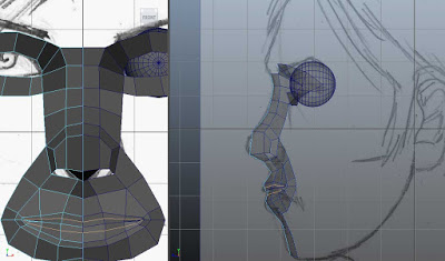
20) Now we want insert another edge loop in the mouth to round it out and add shape. Do this by clicking Edit Mesh > Insert Edge Loop Tool. Insert it where I have inserted mine in the picture above. With the edges or vertices this creates, pull them out to plump up the lips slightly, rounding them out.
21) Now we're going to add shape to the nose, be need a corresponding number of polygons. So add an edge loop under the nose like I have in the picture.

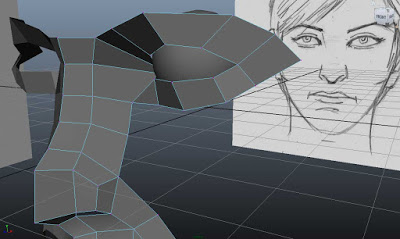
22) Extrude edges out and merge vertices together. At this point, we can also start thinking about the jawline. In side view choose the bottom most polygon edge and extrude it out towards the ear, like the picture in 23).
23) Extrude again at this point and pull up toward the ear.

24) Remember to move things in front and side view simultaneously.
25) Around the chin area, extrude edges and merge vertices to build shape to the face. Also think about the curvature of the chin and the way you arrange your vertices.
26) Keep adjusting and tweaking vertices in side view.

27) Round out the nostrils by selecting each edge around the nostril hole and adding an edge loop. This created more ploys, more vertices and more opportunity to add details to the face.
28) Any edge loop should run the length of the face. Those new ones below the nostril need to continue down the chin, so add one in using the insert edge loop tool. This will also help round out the chin.
29) Adjust as necessary in front or side view.
30) The nose vertices are still quite flat and uniform. Adjust them to create more of a realistic flow around the eye to nose bridge area. Do this by moving the vertices left or right in front view (NOT UP OR DOWN)
31) You've seen how edge loops add detail so add them in wherever you think may be appropriate, but in mind the polygon count and complexity of the mesh.
32) Take the top line of edges across the brow and extrude them upwards to begin to create the forehead.
33) Cover the nostrils by extruding the nostrils edges inwards then pulling them up into the inside of the nose.
Unit 67 - P3 - Animation : Building a skeleton and rigging a model
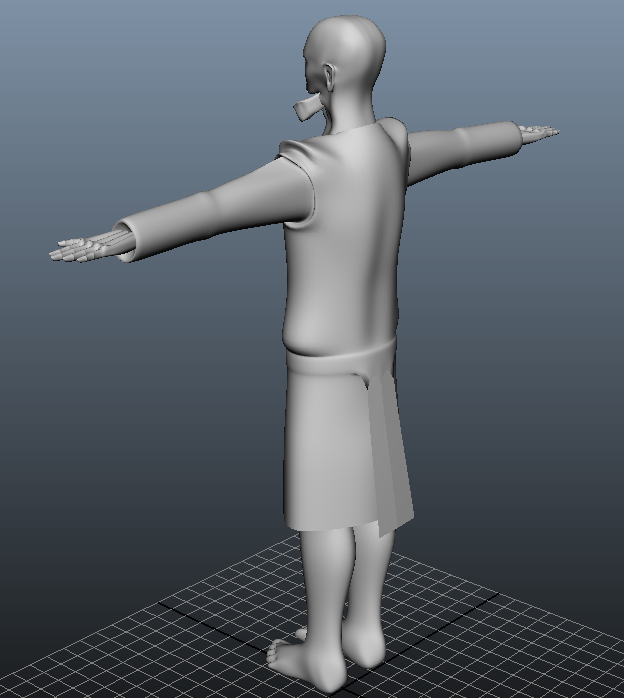
Using the rigging and IK tools in Maya, we can take a model and set up a realistic set of limb joints that we can manipulate. This will enable us to pose and eventually keyframe animate our model. I have documented the process of building a skeleton within a model below, beginning with us positioning our model in the centre of the viewport.
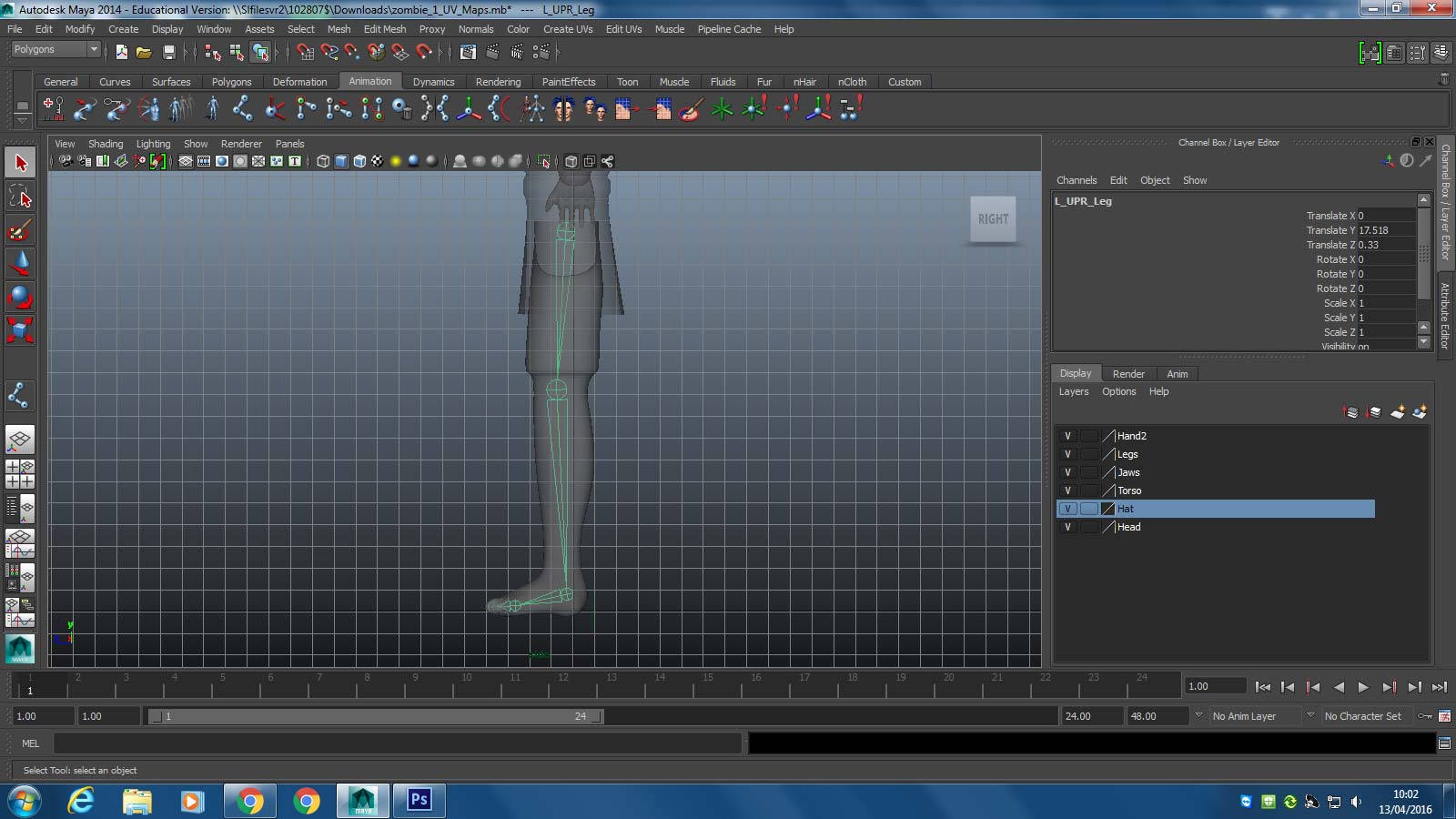
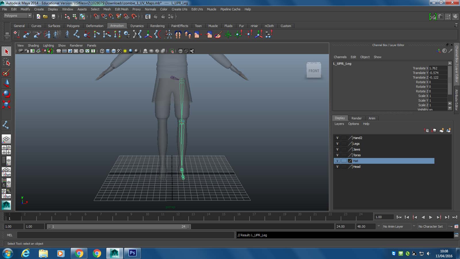
We begin our process on the left leg. Selecting the animation option in the dropdown menu in the top left, we select the build joint tool on the shelf (seventh icon from left). In the side view we draw 5 connecting joints, from the top of the leg, through the foot, to the end of the toe. Already at this stage we need to be thinking about where the joints of the model will bend.
We then go to perspective view and shift the joint set across to sit within the leg. We also name each joint:
L_UPR_leg, L_LWR_leg ,L_foot, L_toe and L_leg_end. The convention of naming each joint with ”L_” is vital - it refers to left leg.
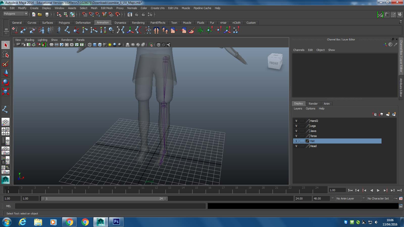
Using our joint tool we can draw a separate joint in the centre which we name “Hips”. By first selecting our left leg joint set and the shift clicking the hip joint we can press “P” on the keyboard. This makes the leg a child of the Parent hip joint - if we move the hips joint, the leg will follow.
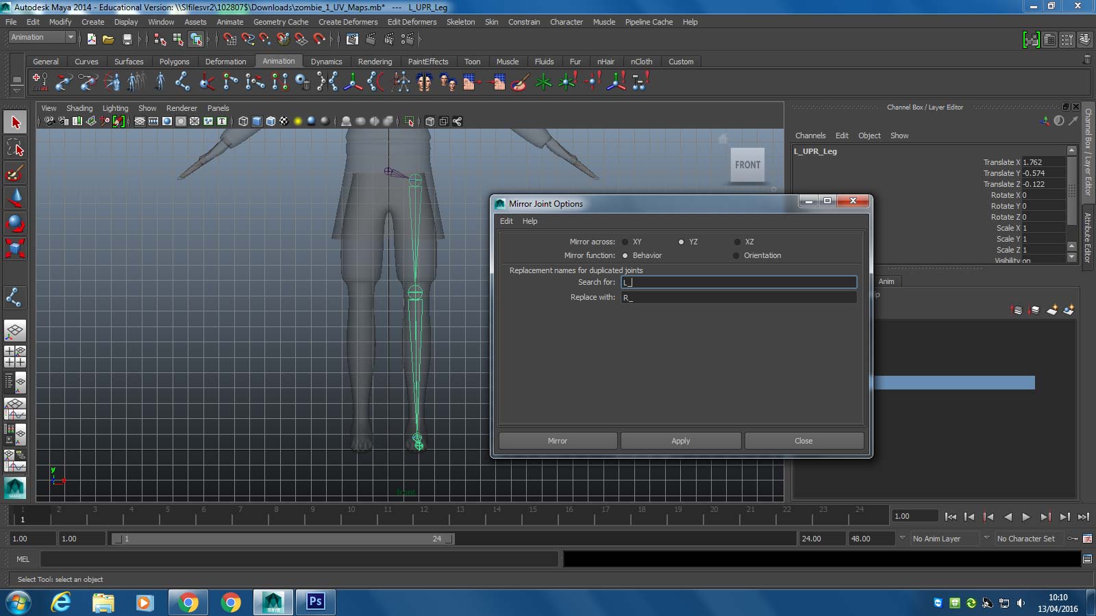
Now by selecting our left leg joint set and choosing the “mirror joint” options box, we can search for “L_” and replace it with “R_”. When we click mirror, the left leg will be duplicated, flipped and have it’s joints renamed with R_.
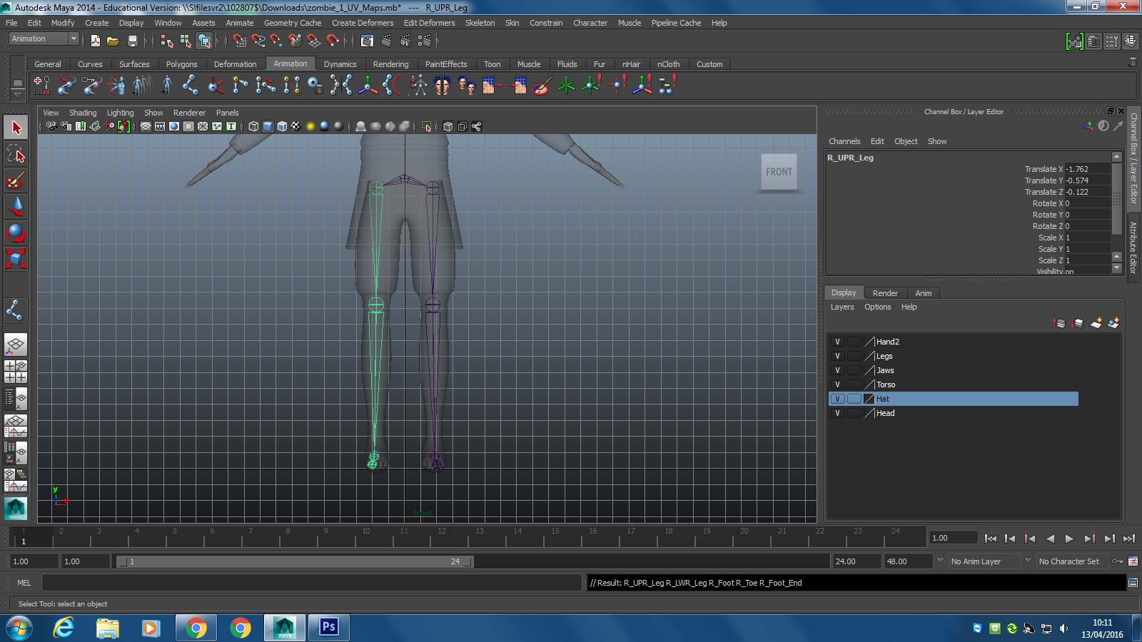
Maya will create a copy of our limb and even recognise it as being a child of the parent hip joint
.
Next we follow the exact same process for the arm. Starting with the left arm we make a new joint set called L_UPR_arm, L_LWR_arm, L_Wrist and L_hand. Additionally, we also make a joint around the collarbone area called L_collarbone and make our left arm joint set a child of the L_collarbone. This means that when L_collarbone is moved, the entire left arm will follow accordingly.
What we also want to do here is make a number of spine joints that run the length of the back, go through the neck and end in a couple for the head.
We take the spine joint nearest the hip and make it a child of the hip joint parent. This means that when the hip moves, the entire spine will move.
Additionally we also make the L_collarbone a child of the spine joint that is nearest to it. Once again, this means that when the spine moves, the left collarbone and arm will follow accordingly.
Next, just like the legs we select the left collarbone and left arm joint set and mirror it, finding replacing L_ with R_ in the mirrored joint set.
With our skeleton complete, we can now bind it to the mesh by shift clicking both and selecting smooth bind from the animation shelf. Now wherever, the skeleton joints move, our mesh will follow.
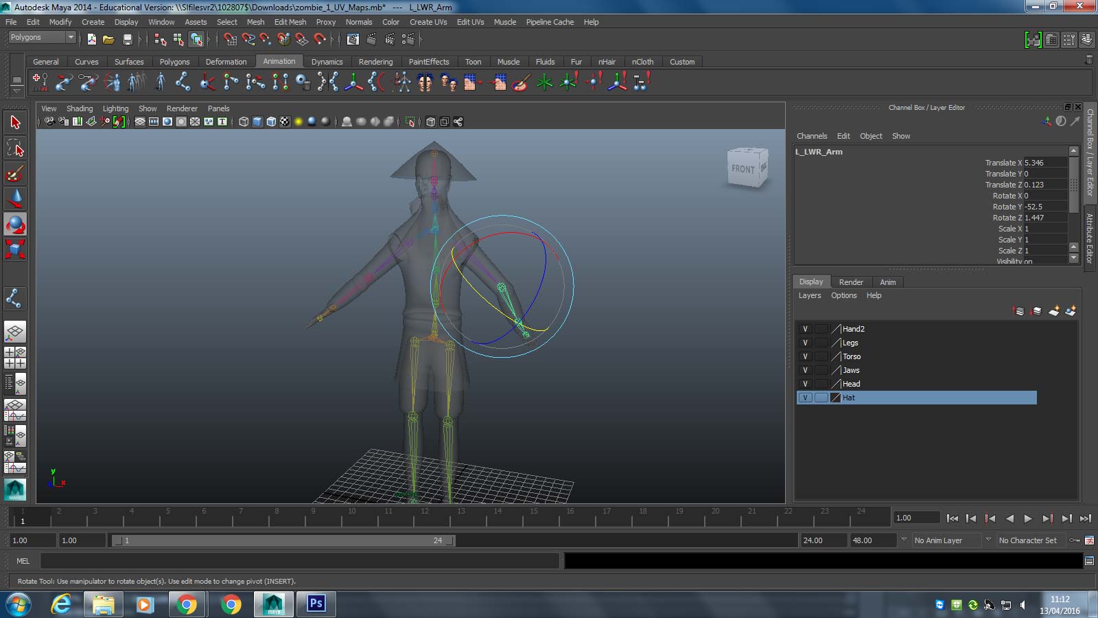
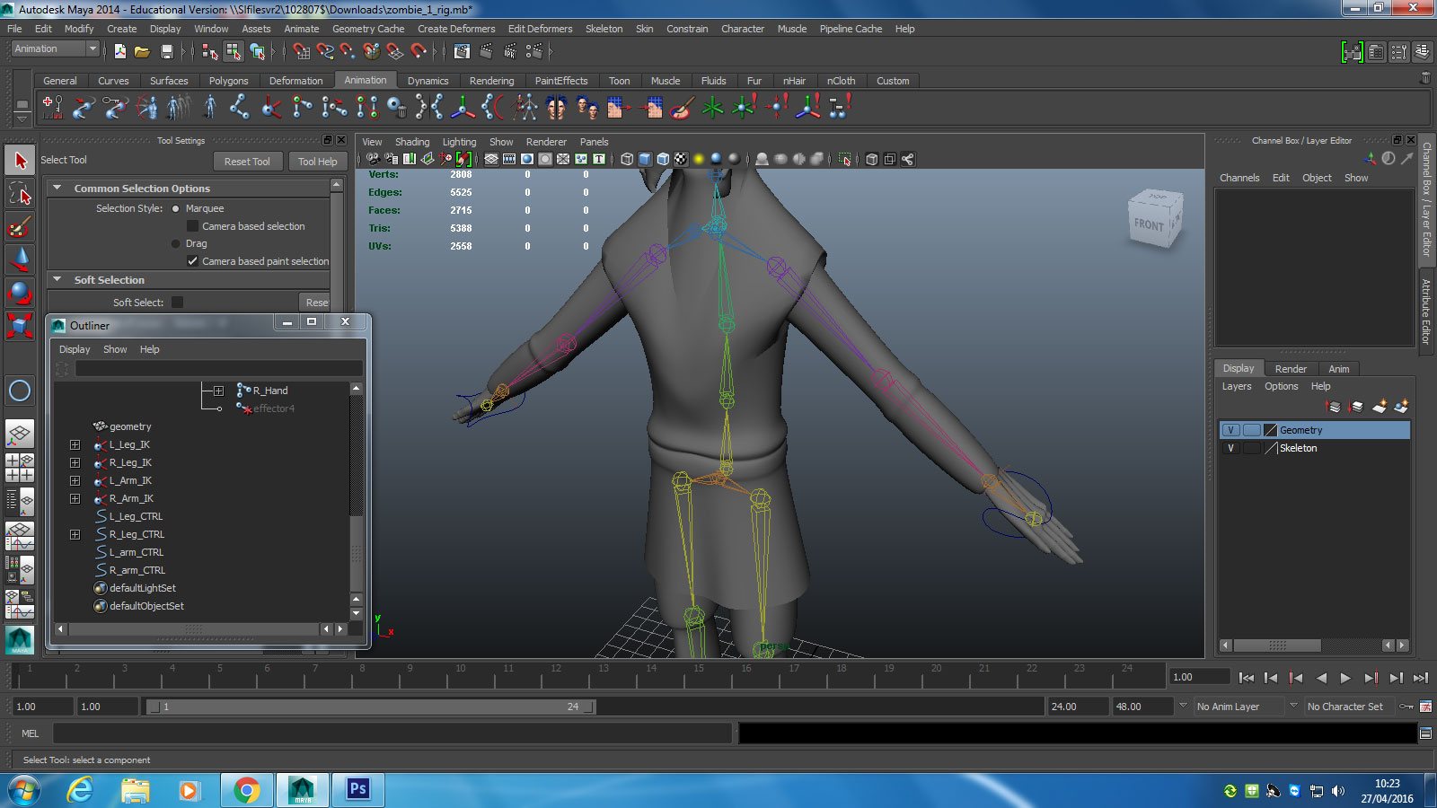
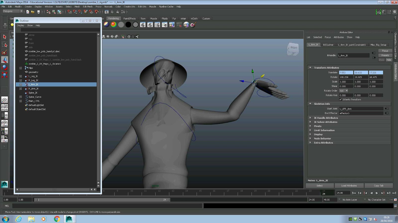
Next we want to set up our IK handles, which is short for ‘Inverse Kinetics’. This is a single controller that runs from one selected joint to another. It appears in the form of a straight line that runs from selected joint A to selected joint B. When we move either of these joints in or out, the joints in between will be pushed accordingly, creating realistic movements such as elbow joints and knee joints (see picture above). We can also rotate the IK handles to twist our limbs realistically. So to set up our IK handles on our limbs we select:
L_foot and L_UPR_leg and click create IK handle on the tool shelf - Makes left leg IK handle
.
Next we follow the exact same process for the arm. Starting with the left arm we make a new joint set called L_UPR_arm, L_LWR_arm, L_Wrist and L_hand. Additionally, we also make a joint around the collarbone area called L_collarbone and make our left arm joint set a child of the L_collarbone. This means that when L_collarbone is moved, the entire left arm will follow accordingly.
What we also want to do here is make a number of spine joints that run the length of the back, go through the neck and end in a couple for the head.
We take the spine joint nearest the hip and make it a child of the hip joint parent. This means that when the hip moves, the entire spine will move.
Additionally we also make the L_collarbone a child of the spine joint that is nearest to it. Once again, this means that when the spine moves, the left collarbone and arm will follow accordingly.
Next, just like the legs we select the left collarbone and left arm joint set and mirror it, finding replacing L_ with R_ in the mirrored joint set.
With our skeleton complete, we can now bind it to the mesh by shift clicking both and selecting smooth bind from the animation shelf. Now wherever, the skeleton joints move, our mesh will follow.
Next we want to set up our IK handles, which is short for ‘Inverse Kinetics’. This is a single controller that runs from one selected joint to another. It appears in the form of a straight line that runs from selected joint A to selected joint B. When we move either of these joints in or out, the joints in between will be pushed accordingly, creating realistic movements such as elbow joints and knee joints (see picture above). We can also rotate the IK handles to twist our limbs realistically. So to set up our IK handles on our limbs we select:
L_foot and L_UPR_leg and click create IK handle on the tool shelf - Makes left leg IK handle
R_foot and R_UPR_leg and click create IK handle on the tool shelf - Makes right leg IK handle
L_hand and L_UPR_arm and click create IK handle on the tool shelf - Makes left arm IK handle
R_hand and R_UPR_arm and click create IK handle on the tool shelf - Makes right arm IK handle
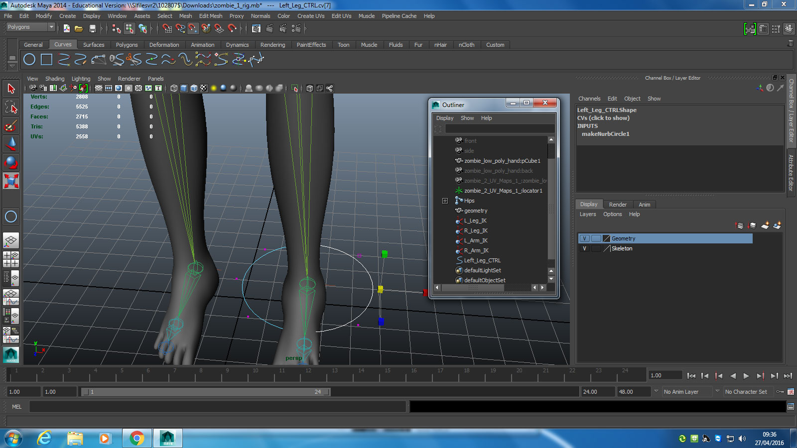
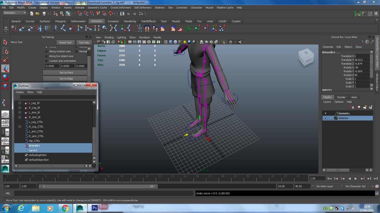
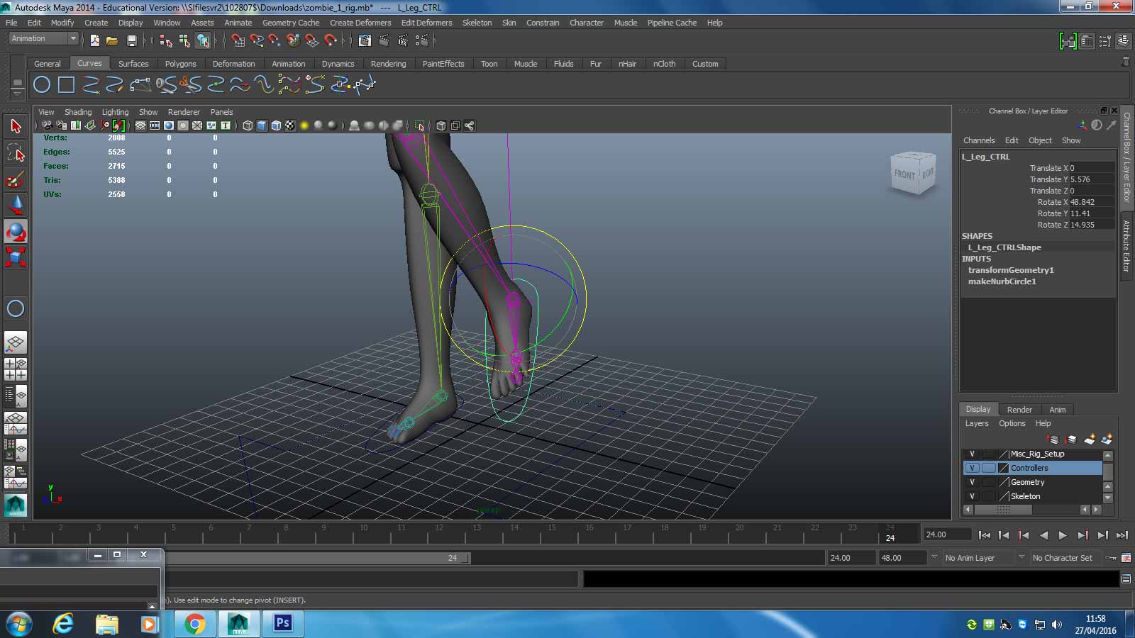
In terms of how we access those IK handles, we need to make an easier way to access them.We can do this by using our curves tool to draw circular control handles and locking them to the IK handles. An IK handle on its own is a relatively narrow handle that can be a little difficult to select. By selecting a much larger handle, we can access an IK easily, along with twisting and rotating the joints nearest to the control handle. We start with our left foot.
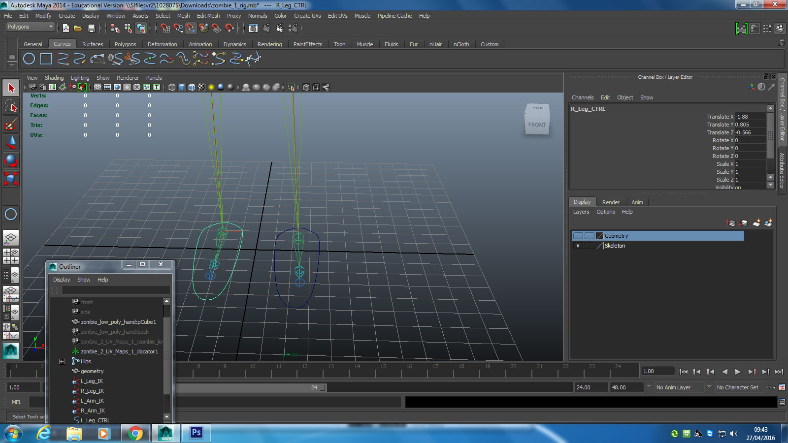
We can then duplicate and create a right foot controller also. On all our controllers we need to click freeze transformations.
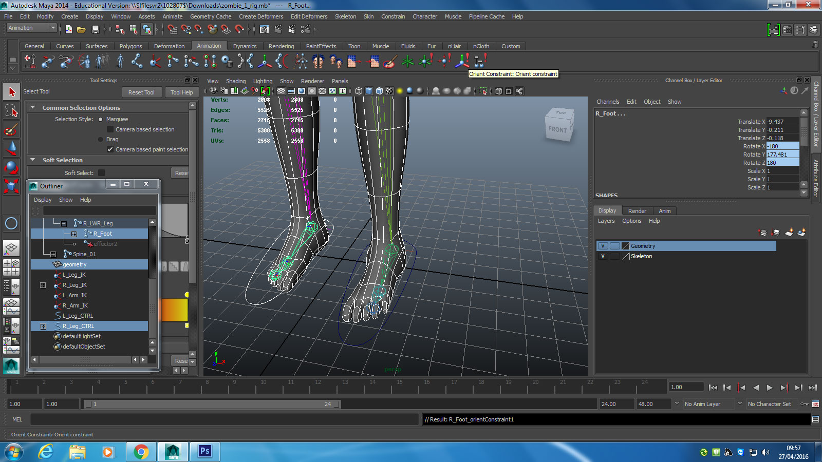
The process of attaching each controller is as follows; we select our relevant curve and IK handle (in the case of the above picture, it is the right foot controller and the right leg IK handle). With both these selected we click constrain to point, meaning that the controller curve is locked to the chosen joint. We then select the controller and the relevant nearby joint and click orient constrain, meaning that where the controller goes, the axis follows.
We obviously then repeat this process to create arm controllers, with the curves locking to the hands and arm IK handles.
Continuing on, we create a hips controller, but we do not hook it up just yet.
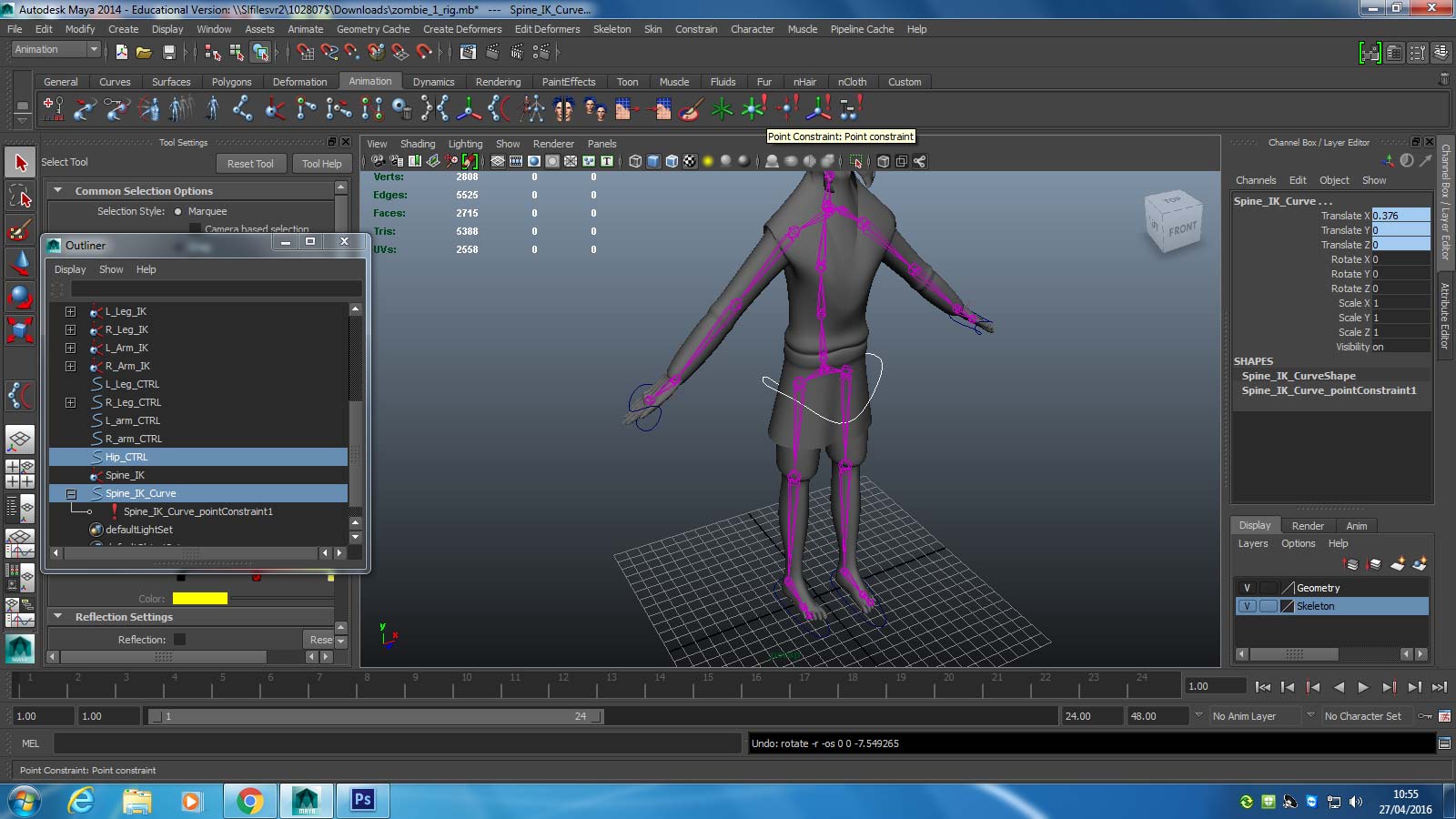
Click the hips joint then the joint where arms are attached. Click IK Spline Handle Tool icon to create a curved spine along the joints we have made (much like the create IK handle process). The spline handle tool creates a special kind of handle that contains vertex sub objects. These sub objects can be manipulated to make a spine bend and curve like a real life one.I will eventually be attached to the spine joints.
We then shift click hips_CTRL and Spine_IK, and click constrain point. Shift click hips_CTRL and Spine_IK_curve and go to orientation constraint hotbox - constrain Z and X axis only. Hit apply.
. The Spine IK curve has features available to it such as roll and twist. We now want to take advantage of the roll (forward and back) channel in the Spine_IK_curve. We do this by doing the following:
In terms of how we access those IK handles, we need to make an easier way to access them.We can do this by using our curves tool to draw circular control handles and locking them to the IK handles. An IK handle on its own is a relatively narrow handle that can be a little difficult to select. By selecting a much larger handle, we can access an IK easily, along with twisting and rotating the joints nearest to the control handle. We start with our left foot.
We can then duplicate and create a right foot controller also. On all our controllers we need to click freeze transformations.
The process of attaching each controller is as follows; we select our relevant curve and IK handle (in the case of the above picture, it is the right foot controller and the right leg IK handle). With both these selected we click constrain to point, meaning that the controller curve is locked to the chosen joint. We then select the controller and the relevant nearby joint and click orient constrain, meaning that where the controller goes, the axis follows.
We obviously then repeat this process to create arm controllers, with the curves locking to the hands and arm IK handles.
Continuing on, we create a hips controller, but we do not hook it up just yet.
Click the hips joint then the joint where arms are attached. Click IK Spline Handle Tool icon to create a curved spine along the joints we have made (much like the create IK handle process). The spline handle tool creates a special kind of handle that contains vertex sub objects. These sub objects can be manipulated to make a spine bend and curve like a real life one.I will eventually be attached to the spine joints.
We then shift click hips_CTRL and Spine_IK, and click constrain point. Shift click hips_CTRL and Spine_IK_curve and go to orientation constraint hotbox - constrain Z and X axis only. Hit apply.
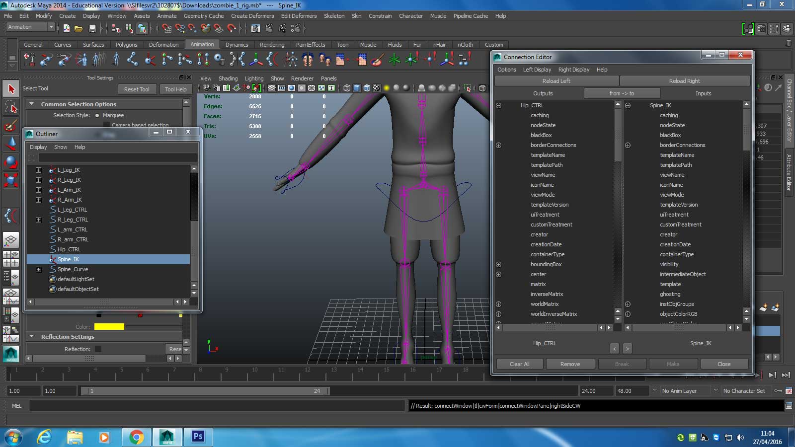
. The Spine IK curve has features available to it such as roll and twist. We now want to take advantage of the roll (forward and back) channel in the Spine_IK_curve. We do this by doing the following:
Go to Window > General Editors > Connection Editor
Find Hip_CTRL in the outliner
Hit Load Left button in the Connection Editor
Find Hip_CTRL in the outliner
Hit Load Left button in the Connection Editor
Find rotate and expand
Highlight rotateY
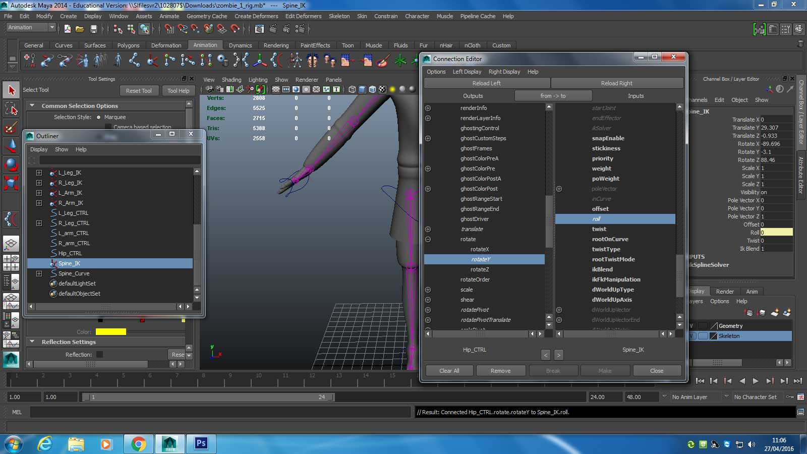
Find Spline_IK in the outliner
Hit Load Right button in the Connection Editor
Hit Load Right button in the Connection Editor
Find roll and highlight
Duplicate Hips_CTRL and rename it Chest_CTRL - snap to spine joint in chest area, that is also attached to the collar bones
Find Chest_CTRL in the outliner
Hit Load Left button in the Connection Editor
Hit Load Left button in the Connection Editor
Find rotate and expand
Highlight rotateY
Find Spline_IK in the outliner
Hit Load Right button in the Connection Editor
Hit Load Right button in the Connection Editor
Find twist and highlight
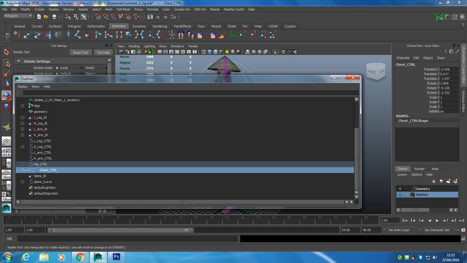
Make Hips_CTRL parent and Chest_CTRL a child.
Make Left_Arm_CTRL and Right_Arm_CTRL children of Chest_CTRL (This means when the chest moves, the arms will follow).

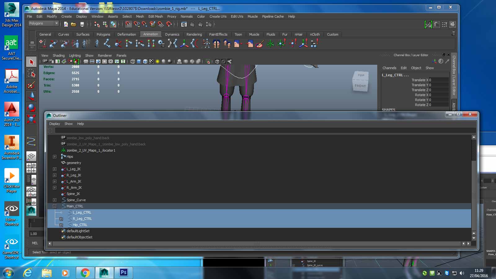
If we wish, we can make a large main controller by drawing a large arrow on the floor and making all our controllers children of the main parent controller.
Setting up skin weights
Skin weights can be adjusted to prevent deforming when the model bends. The heavier the skin, the more rigid it is and so the less likely it is to deform upon bend.
We can begin to test our skin for deformation by moving the IK handles to bend the limbs. We can also rotate the controller handles we set up.
For example, we have discovered that if we set up a head control curve, attach it to the head joint and rotate, the head will begin to distort. To fix this we go to our animation menu and choose skin. From here we select the paint skin weights option hotbox.

The joint list should come up in a menu on the right. By selecting each joint we can see in white highlighted areas just how rigid the skin is on that part of the mesh.If it is more grey than white, the skin is quite malleable. If it is solid white it is rigid. We can use a paintbrush tool to paint in whiter areas on malleable parts or make rigid parts more malleable by selecting ‘replace’ rather than ‘add’ in the menu.
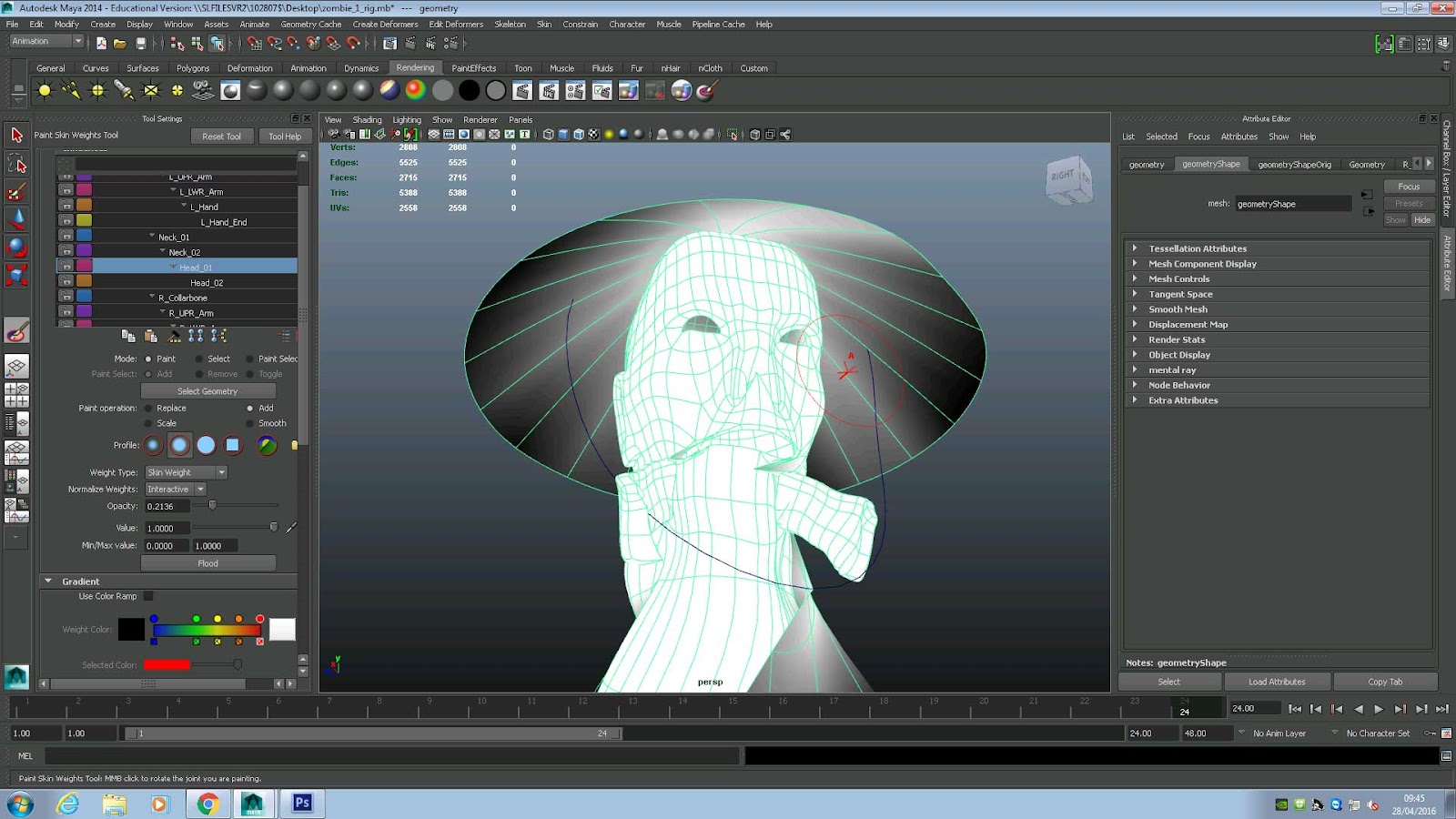
In the picture above you can see how painting the head white has made the skin more rigid, resulting in it not deforming any more when the head turns.
Concept design work
The following describes in brief what my enemy characters were intended to achieve during the animation stage. Due to time constraints and technical limitations, I had to compromise my ideas, but hopefully the sketches below will give some idea of what I had in mind.
The following describes in brief what my enemy characters were intended to achieve during the animation stage. Due to time constraints and technical limitations, I had to compromise my ideas, but hopefully the sketches below will give some idea of what I had in mind.
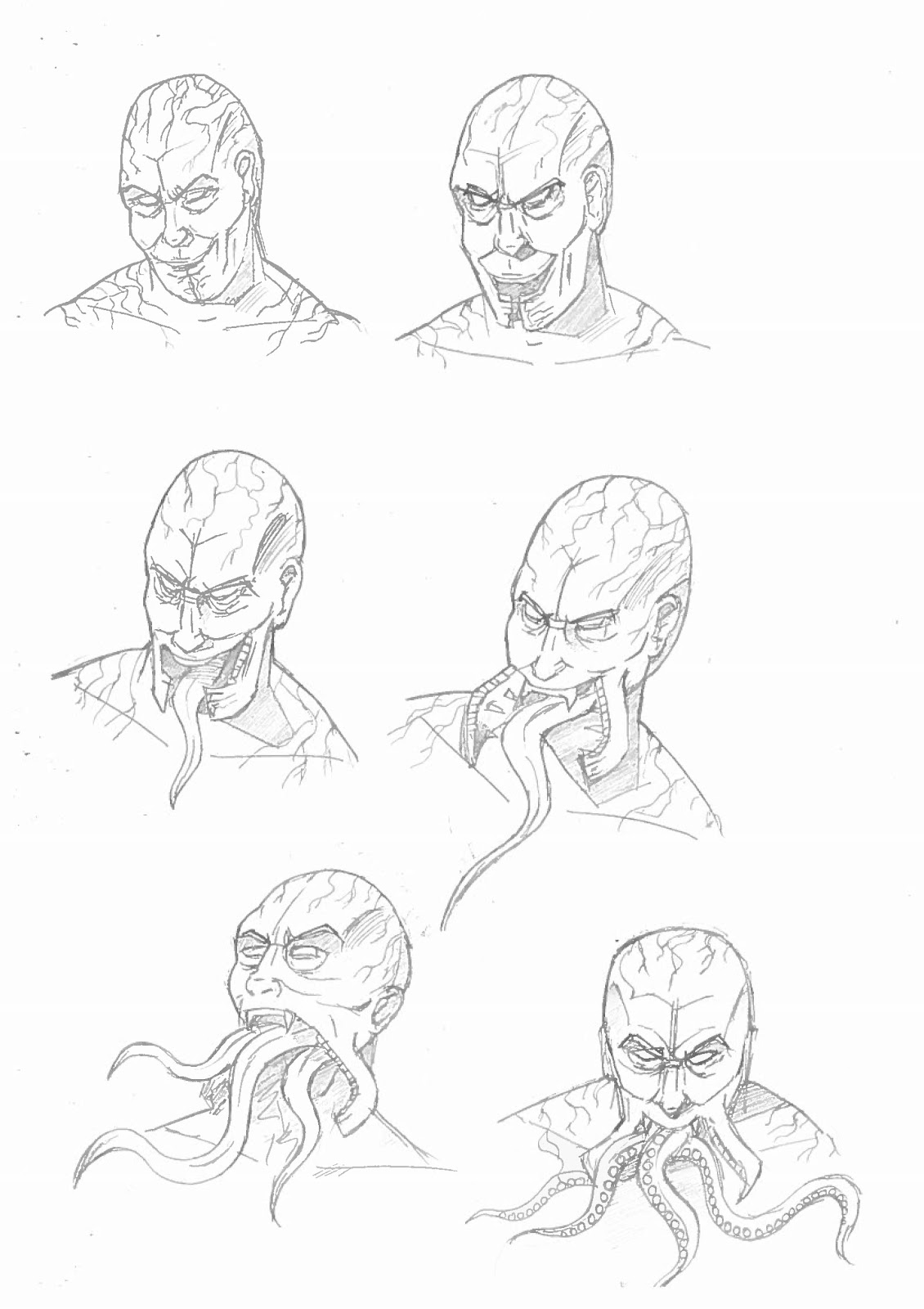
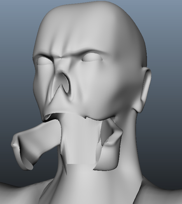
The zombies are humans that are infected by a small waterborne parasite. Microscopic and able to travel undetected through water, the small squid like quickly grows inside a human host. One of the main features of the infected human hosts was to have the growing parasite alter them genetically - they will have jaws that open and split down the middle, allowing the many internal tentacles to make themselves known. The above sketch shows the process of how this would happen, transforming an innocent looking person into a hideous creature.

Sketches showing small incidental animation ideas throughout the levels of the game.
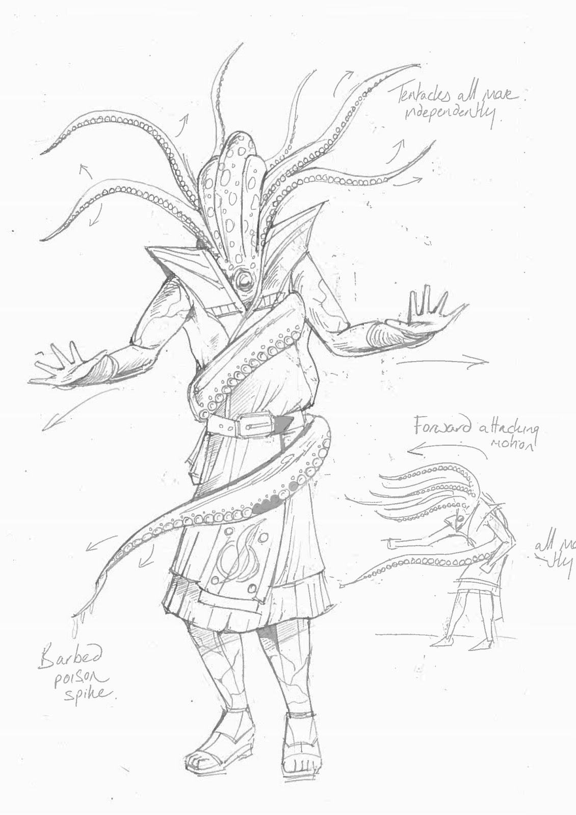
Fully grown parasites eventually break through and destroy the human head, replacing it with a squid like mass of tentacles that deadly in combat. The above sketches demonstrate this in action. Note the large tentacle wrapping around the body which plays host to a poisoned barb.

The zombies would feel their way through an environment with outstretched arms, as demonstrated in the above sketches.
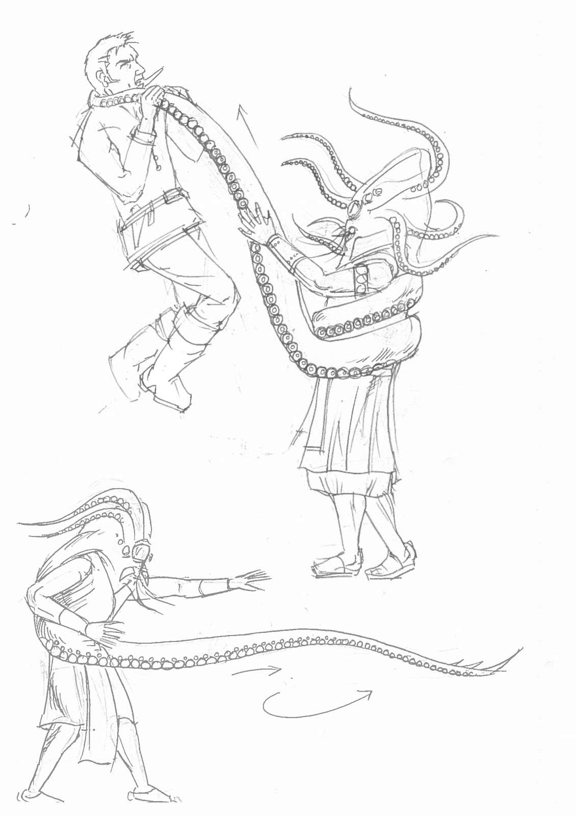
Sketches demonstrating how the zombies would attack the player.
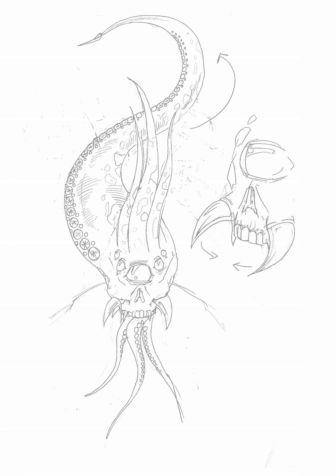
A sketch of the way that a fully grown zombies tentacled head will unfurl. Additionally, an idea for the movement of a strange pair of protruding mandibles.

Infected humans will walk with a lurching, awkward gait, very much as if they are being controlled like puppets from the internal parasite.
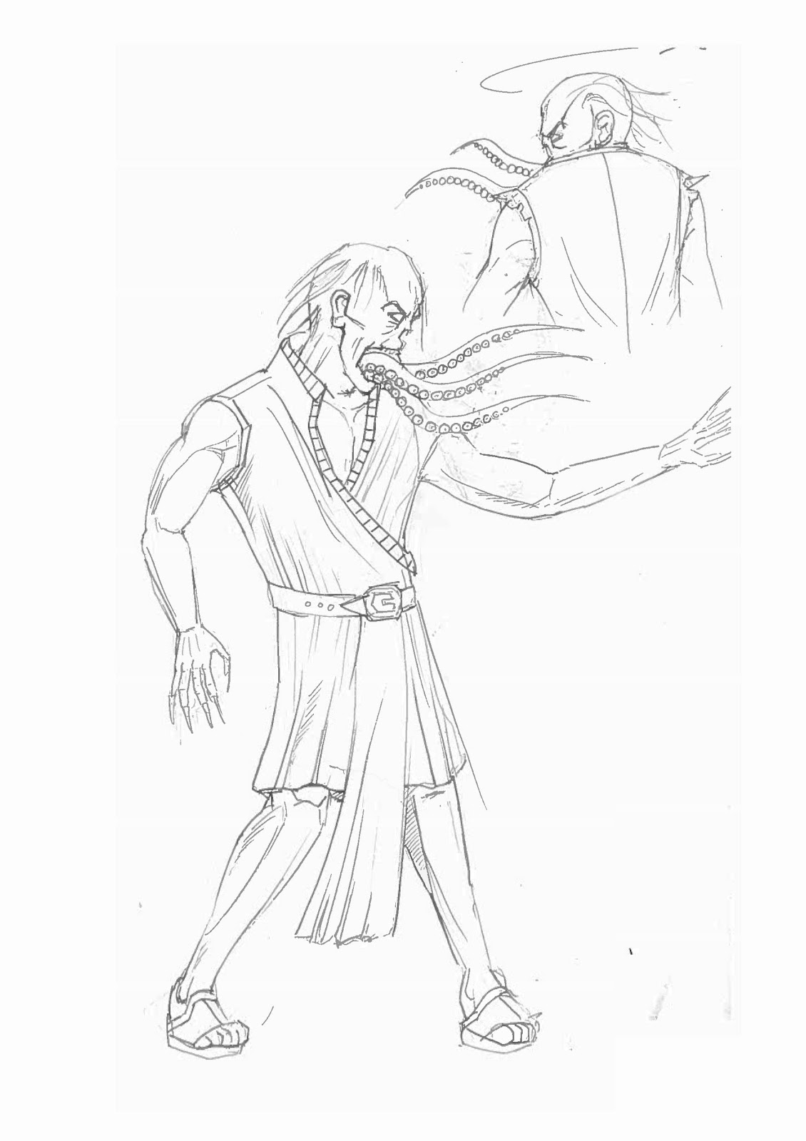
Infected humans will walk with a lurching, awkward gait, very much as if they are being controlled like puppets from the internal parasite.
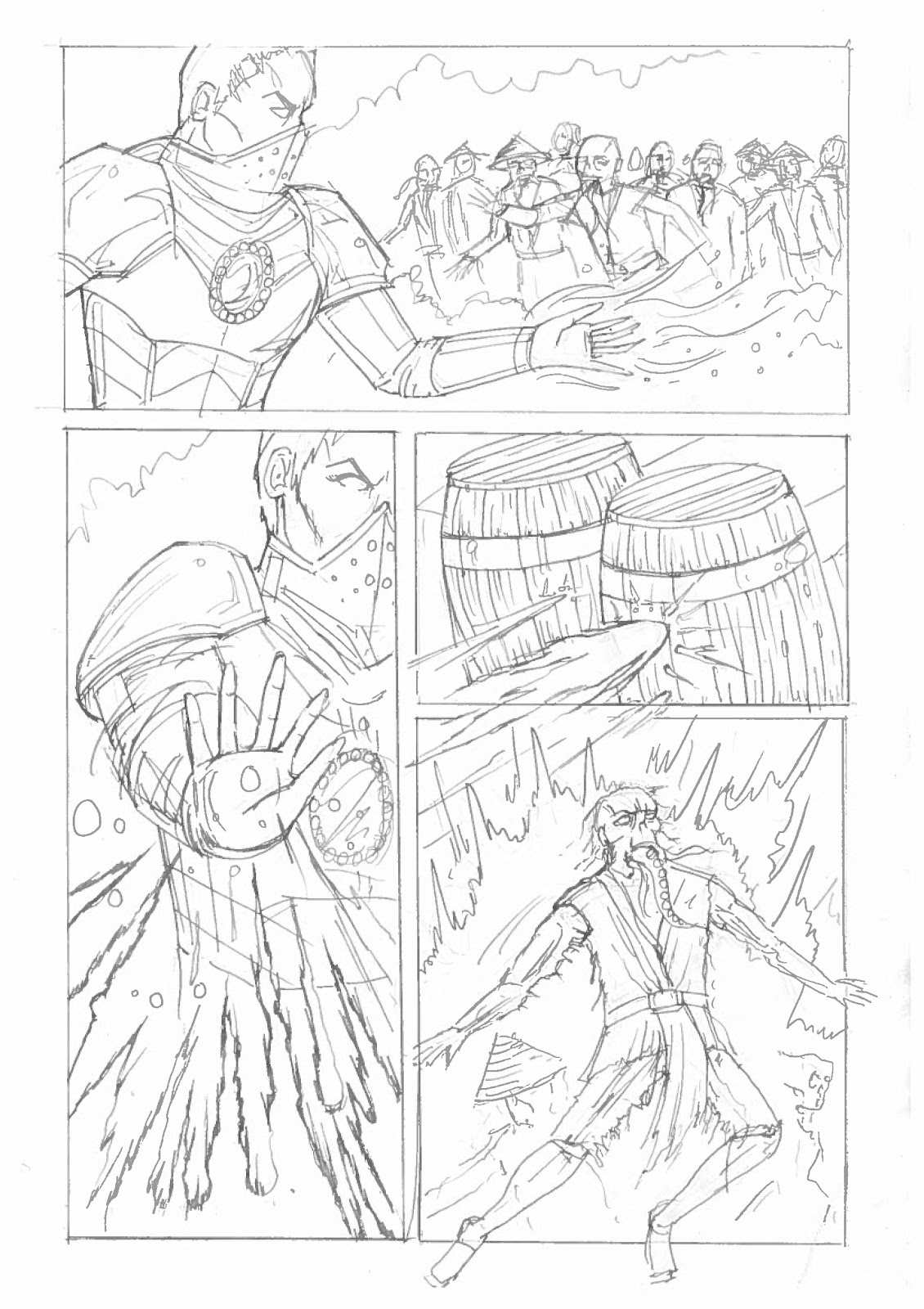
A short storyboard showing how explosive barrels will have an impact on the zombies when they explode. Strategically shooting them will allow the player to take out large groups of zombies and add to the action.
Screenshots of my final models - main character and zombies
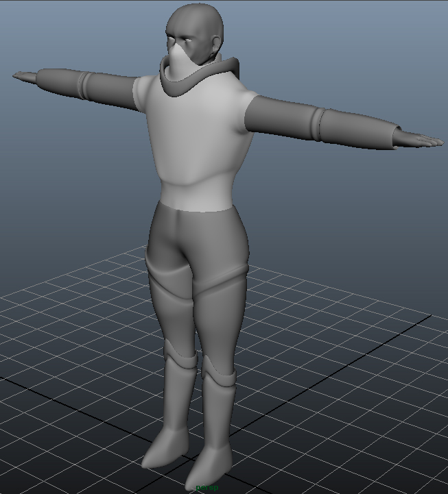
Armoured female - main character
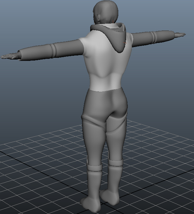
Armoured female - main character

Armoured female - main character
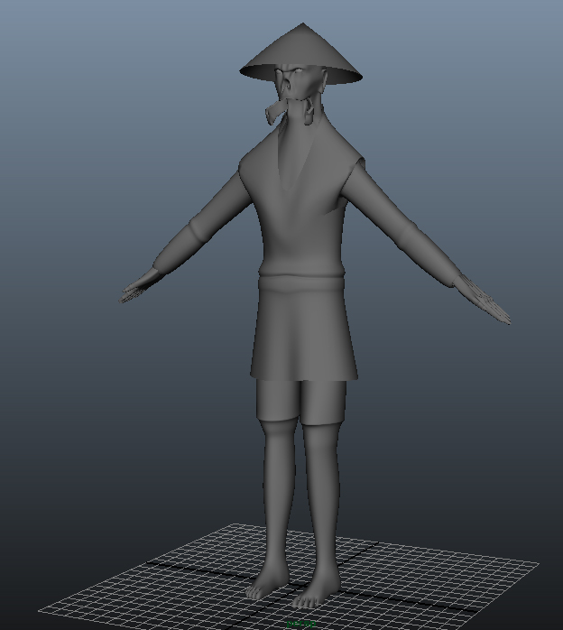
Zombie 1
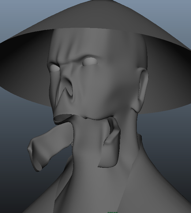
Zombie 1
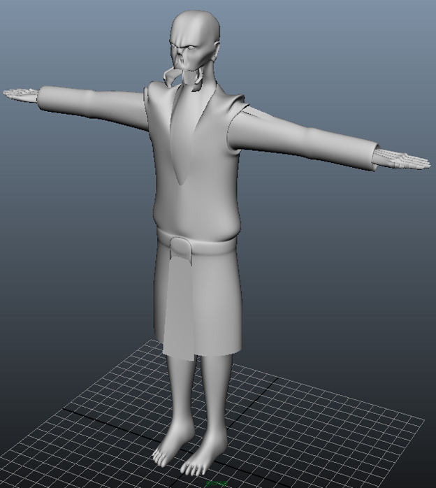
Zombie 2
Zombie 2
Zombie 2
Links to videos showing animation tests and gameplay animation
Gameplay walkthrough videos:
Level 1 & 2
https://www.youtube.com/watch?v=T2tef8uODtc
Level 3
Animation test
https://www.youtube.com/watch?v=FJoL7EfW0nM&feature=youtu.be
No comments:
Post a Comment