Blueprinting is a visual programming method used in Unreal 4 to tie all the separate elements together. Below I have attempted to describe several of the methods I have used to add interactivity to the game I have been developing:
AI
Setting up an enemy with some artificial intelligence that reacts to the player position is a fairly simple job. The following screenshots demonstrate the process with which this is achieved. All of this is set up within an actor blueprint called Enemy AI_1.
Setting up an enemy with some artificial intelligence that reacts to the player position is a fairly simple job. The following screenshots demonstrate the process with which this is achieved. All of this is set up within an actor blueprint called Enemy AI_1.
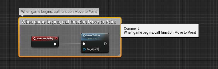
When the game begins we set up a simple function node that tells the enemy actor to immediately move to a designated point on the map. The function logic flow is described below:
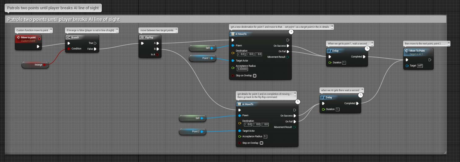
While the enemy is moving, we need to check a few things - is the player within the enemy’s line of sight? If it is, run towards the player to attack. This is determined by a simple variable called inrange. If the player is in range of the enemy this variable will be set to true. If it is false , the logic above will carried out. This true / false condition is carried out by what is known as a branch. If true, the enemy will attack the player. If not, the enemy should ‘flip flop’ between two points, pausing for a second at each before running to the other.
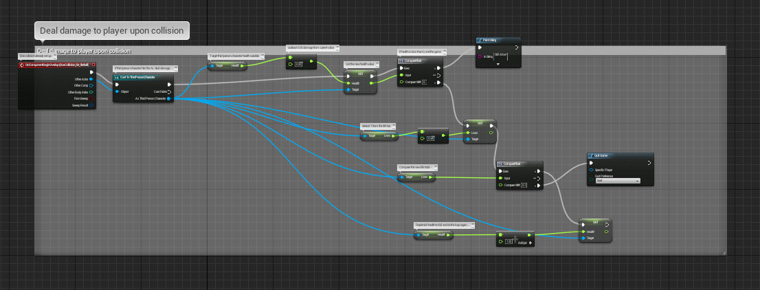
When our enemy collides with the player, we want to subtract some percentage from the player’s overall health. With every collision we want to make a comparison with the value of the health variable to see exactly what state the player is in. When the player’s health bar falls below zero, we want to subtract 1 of the player’s 3 lives, and recharge the health bar to maximum for the next life. When all 3 lives are lost, we want the game to quit. We can also flash up a message on screen that tells the player that they have sustained damage, but are still alive.
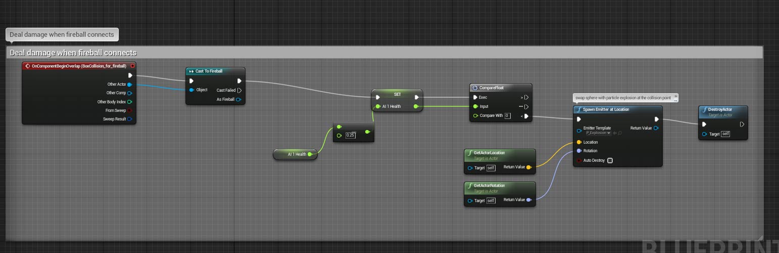
The player fireball should connect with the enemy and cause a collision to trigger, subtracting health from the enemy. This is similar to the player’s health system described above with with a few tweaks. With every hit, the fireball deducts 25% damage from the overall enemy health. Every time this happens, the enemy health variable is set to a new value. If the enemy health variable has not yet reached zero, this process will repeat until it does.
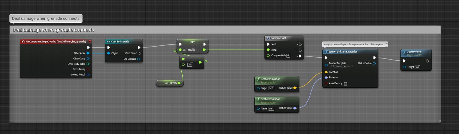
.When the enemy health reaches zero, we want to swap the enemy actor for an explosion emitter, then destroy the instance. This is done by comparing the current value of the health variable to zero with every hit. When at last the comparison is true, the explosion emitter will trigger, signifying the death of the enemy.
The explosion emitter makes sure it is appearing in the right place by getting the exact coordinates of where the enemy actor last was on the map. This is achieved through the ‘GetActorLocation’ and ‘GetActorRotation’ nodes.
The player’s second weapon, the grenade will kill the enemy on impact The process works exactly the same as the fireball above, but causes far more damage per collision resulting in a quicker death for the enemy.
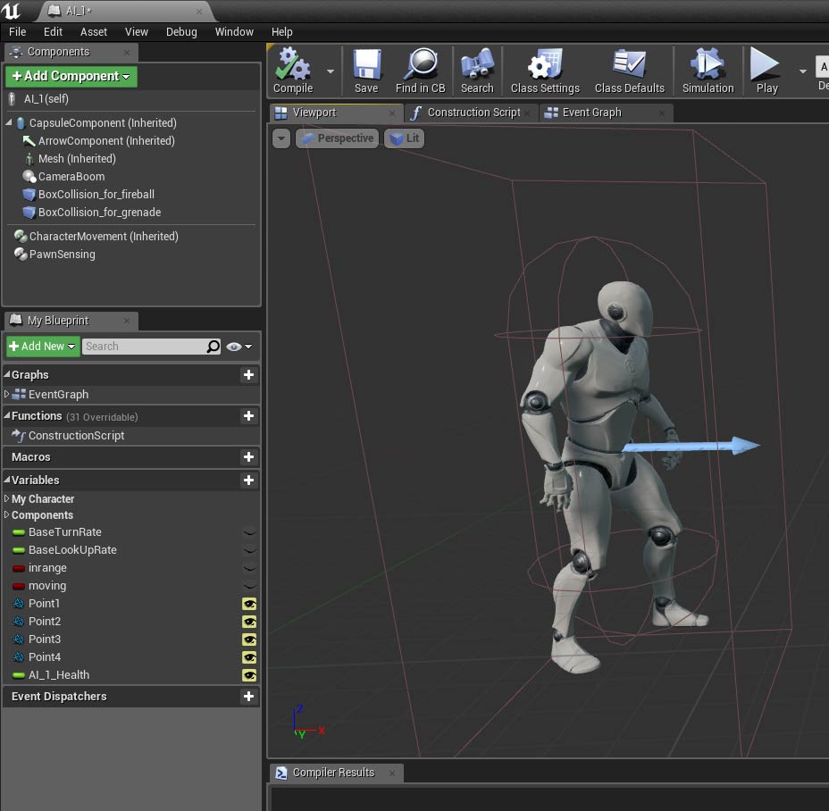 | Both of the fireball and grenade collisions need their own collision boxes to register what has hit the enemy actor. It is not possible to have one collision box for two different types of player weapon effects. This is the viewport, which allows to see visually what elements currently make up the enemy actor. You can see both types of collision box in the component list on the left hand side of the screenshot. They are labelled:
Also in the menu on the left, under the ‘My Blueprint’ tab, you can see all the variables that the Blueprint intends to reference, including whether the player is in range (a simple true or false) and the current value of the enemy’s health, as described above |
HUD
Setting up the heads up display to record the state of the player’s health, magic meter. Grenades and lives remaining is a reasonably simple process. It begins by making a simple widget blueprint and naming it ‘GameMode’. It is placed inside a folder called ‘UMG’ (short for Unreal Motion Graphics). Our first step is to open the newly created widget opening up the designer view.
Setting up the heads up display to record the state of the player’s health, magic meter. Grenades and lives remaining is a reasonably simple process. It begins by making a simple widget blueprint and naming it ‘GameMode’. It is placed inside a folder called ‘UMG’ (short for Unreal Motion Graphics). Our first step is to open the newly created widget opening up the designer view.
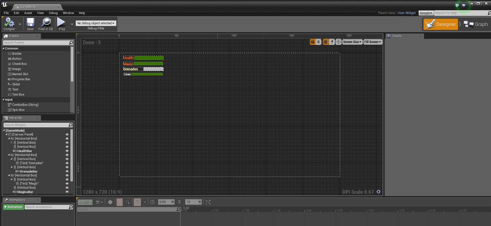
From here, we create a series of name labels and progress bars, positioning them inside horizontal and vertical boxes. The white box on the grid above represents our computer monitor screen, or overall play area. Inside our third person character blueprint, we should also have set up a number of float variables to represent health, magic, grenades and lives.
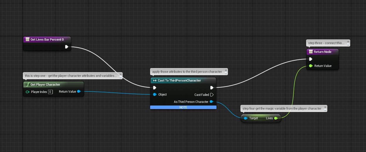
We bind the variables to the progress bars and for each one we bind, are given the option to build a blueprint. The above example is for the lives bar. From the purple node in the top left, we are first telling Unreal to bind the lives progress bar to the actions and state of the third person character (TPC). The TPC blueprint obviously contains the variables we are working with, so by stating the ‘Get Player Character’ node, we pull in all the information and variables associated with it.Because we did this, we can then target the current value of the ‘Lives’ variable and return it’s value to the progress bar. The progress bar is smart enough to know that a variable value of say, 0.75 will equate to 75% of the bar being filled.
Third Person Character
One of the trickier and more demanding blueprints to complete is the one concerning the TPC. The information it carries is in a constant state of flux, from states through to current position in the world. Beginning with the task of assigning the key F to shoot fireballs, we go back to the TPC blueprint and begin to create conditional checks and functionality:
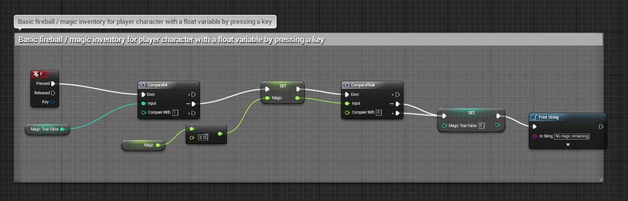
On the far left, in red, we can see a node for the event concerning a press of F on the keyboard. I already set up a variable called ‘Magic True False’ to see if the player’s magic meter is full or empty. If it is full the value is 1, for true. If not it is 0 for false. This is the first comparison check that is performed. If equal to 1 the logic flow can proceed. The next step involves setting the magic variable with a new value - after all the player has just pressed the F key to fire, so some of the ‘Magic’ variable should be deducted. This is reflected in the instantly updated progress bar in the HUD (see above). The next step checks to see if the magic meter is now empty. If it is the ‘Magic True False’ variable is set to 0 and a string carrying an appropriate message is printed on screen. This obviously means that if the player were to press F again, the whole sequence would attempt to repeat but nothing would happen as the logic flow would not get past the very first initial comparison.
If after shooting the magic meter is still full however, the last comparison is ignored and the sequence can be repeated to shoot another projectile.
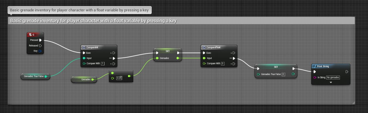
Other weapons such as the grenade are processed in exactly the same way. Logic flows can be reused by referencing different variables.
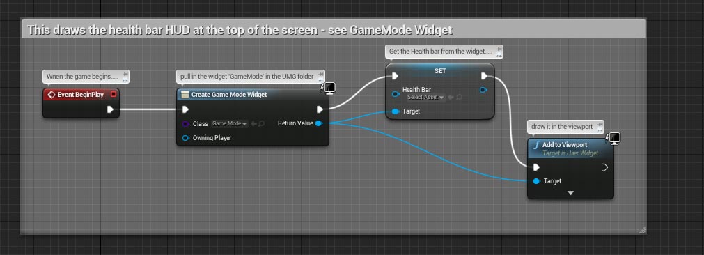
Remember the HUD widget ‘GameMode’ from earlier? This is the little bit of logic that draws it on the screen in the specified position. The red node on the left is an ‘Event BeginPlay’ which tells the logic to do something as soon as the game starts. In this case the widget is added to the viewport.
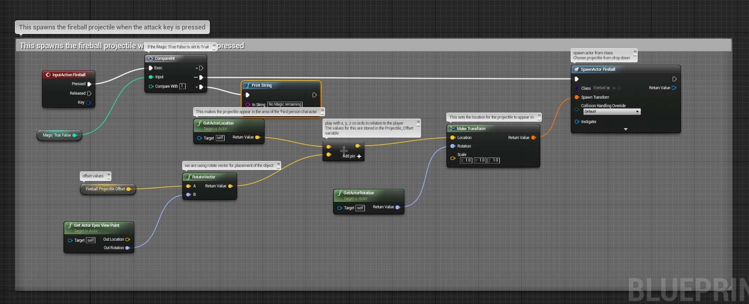
This is where the logic determines how to create a projectile on screen when the F key is pressed. We previously set up the Input action ‘Fireball’ as a key press of F. The first thing the logic does is check if the ‘Magic True False’ meter is set to 1 or 0 (full or empty.) If it is 1, the logic can proceed. If 0, an appropriate string message is printed on screen. Our fireball actor is a separate actor blueprint that contains the effects and velocity information. If the logic can proceed, the first thing we do is spawn this fireball actor. It’s appearance location is determined by the location of the TPC on screen. Much of the above logic concerns which way the actor is facing as well as where they are, so the fireball actor is spawned facing in the right direction of the TPC. Due to the setup of speed and velocity within the fireball actor blueprint it should then fly from this position and travel across the screen.
An interesting element to note here is the reference to the ‘Fireball Projectile Offset’, the small yellow node on the bottom left of the screen. This offset takes the TPC actor blueprint and allows the fireball actor blueprint to appear anywhere around it via X,Y,Z coordinates as an offset. If we wanted to shoot the fireball from the actors eyes or hands, this is where we would do it by altering the offset slightly.
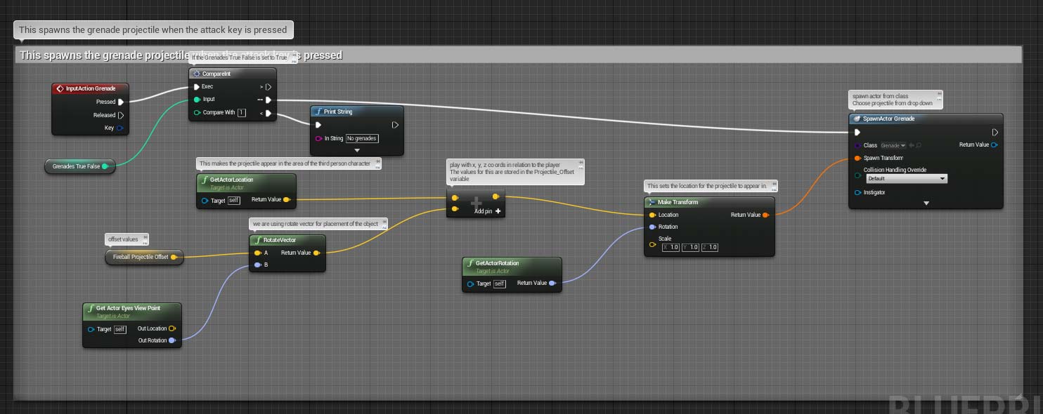
This is where the logic determines how to create a grenade projectile on screen when the G key is pressed. We previously set up the Input action ‘Grenade’ as a key press of G. The first thing the logic does is check if the ‘Grenades True False’ meter is set to 1 or 0 (full or empty.) If it is 1, the logic can proceed. If 0, an appropriate string message is printed on screen. Our Grenade actor is a separate actor blueprint that contains the effects and velocity information. Unlike the fireball actor, it also includes elements such as friction, gravity and rolling. These will alter how the grenade acts with the environment when it is thrown - it can be heavy or light so may bounce off obstacles or be stopped on impact with them.
If the logic can proceed, the first thing we do is spawn this grenade actor. It’s appearance location is determined by the location of the TPC on screen. Much of the above logic concerns which way the actor is facing as well as where they are, so the grenade actor is spawned facing in the right direction of the TPC. Due to the setup of speed and velocity within the grenade actor blueprint it should then fly from this position and travel across the screen.
If after shooting the magic meter is still full however, the last comparison is ignored and the sequence can be repeated to shoot another projectile.
Other weapons such as the grenade are processed in exactly the same way. Logic flows can be reused by referencing different variables.
Remember the HUD widget ‘GameMode’ from earlier? This is the little bit of logic that draws it on the screen in the specified position. The red node on the left is an ‘Event BeginPlay’ which tells the logic to do something as soon as the game starts. In this case the widget is added to the viewport.
This is where the logic determines how to create a projectile on screen when the F key is pressed. We previously set up the Input action ‘Fireball’ as a key press of F. The first thing the logic does is check if the ‘Magic True False’ meter is set to 1 or 0 (full or empty.) If it is 1, the logic can proceed. If 0, an appropriate string message is printed on screen. Our fireball actor is a separate actor blueprint that contains the effects and velocity information. If the logic can proceed, the first thing we do is spawn this fireball actor. It’s appearance location is determined by the location of the TPC on screen. Much of the above logic concerns which way the actor is facing as well as where they are, so the fireball actor is spawned facing in the right direction of the TPC. Due to the setup of speed and velocity within the fireball actor blueprint it should then fly from this position and travel across the screen.
An interesting element to note here is the reference to the ‘Fireball Projectile Offset’, the small yellow node on the bottom left of the screen. This offset takes the TPC actor blueprint and allows the fireball actor blueprint to appear anywhere around it via X,Y,Z coordinates as an offset. If we wanted to shoot the fireball from the actors eyes or hands, this is where we would do it by altering the offset slightly.
This is where the logic determines how to create a grenade projectile on screen when the G key is pressed. We previously set up the Input action ‘Grenade’ as a key press of G. The first thing the logic does is check if the ‘Grenades True False’ meter is set to 1 or 0 (full or empty.) If it is 1, the logic can proceed. If 0, an appropriate string message is printed on screen. Our Grenade actor is a separate actor blueprint that contains the effects and velocity information. Unlike the fireball actor, it also includes elements such as friction, gravity and rolling. These will alter how the grenade acts with the environment when it is thrown - it can be heavy or light so may bounce off obstacles or be stopped on impact with them.
If the logic can proceed, the first thing we do is spawn this grenade actor. It’s appearance location is determined by the location of the TPC on screen. Much of the above logic concerns which way the actor is facing as well as where they are, so the grenade actor is spawned facing in the right direction of the TPC. Due to the setup of speed and velocity within the grenade actor blueprint it should then fly from this position and travel across the screen.
Key collecting
A gameplay element I was keen to include involves collecting keys to open locked doors. The player cannot proceed through the game world if they have not worked out how to navigate through these obstacles. The process below describes my thinking for how I put the logic together:
A gameplay element I was keen to include involves collecting keys to open locked doors. The player cannot proceed through the game world if they have not worked out how to navigate through these obstacles. The process below describes my thinking for how I put the logic together:
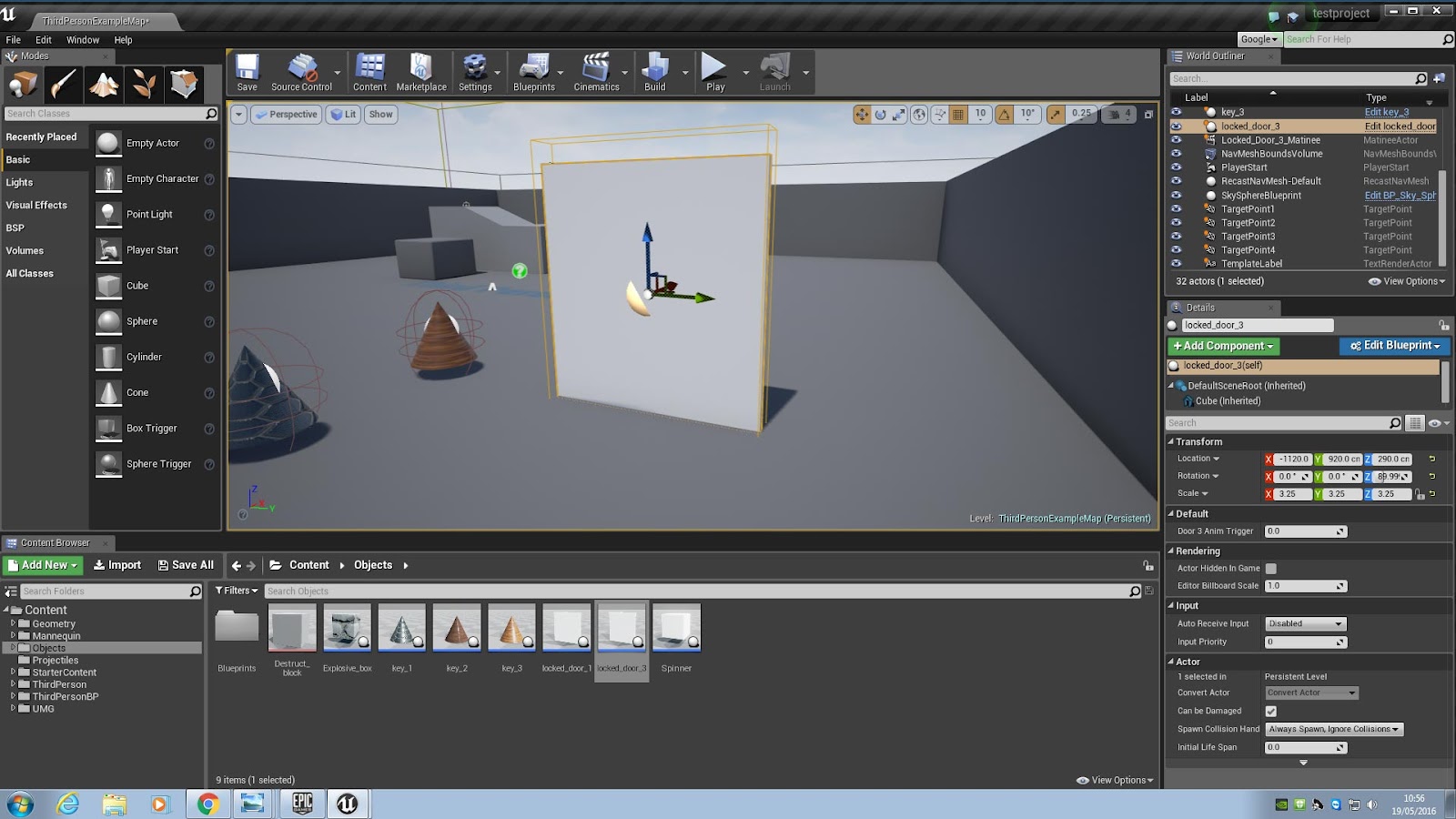
I made the door first that is surrounded by an invisible trigger box. When the player enters this trigger box, a logic flow is carried out to determine whether the three keys have been collected or not. The keys are also individual actors who carry a true / false variable to say whether they have been picked up or not. These are referenced by the door actor. I decided that if the player had all three then the door would slide down into the ground via an animation.
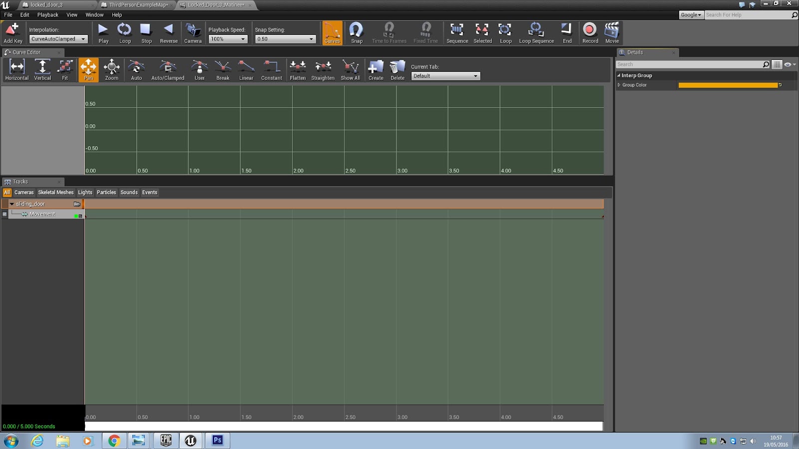
A level animation in Unreal is called a matinee. Above is the screen for setting up a matinee - we access by clicking the menu at the top of the viewport. Following this we create the movement by performing these actions:
1) Select the door in the viewport.
2) In the left hand section of the bottom half of the screen we right click the vertical grey section and choose ‘Add new group’. We name it.
3) With the door still selected in the viewport, we right click this new group and choose ‘Add selected actors’.
4 )Under this group we right click and select ‘Add movement track’.
5) In the bottom half of the screen we drag out the green timeline to about 5 seconds in.

6) With our timeline marker at the 5 second mark, we then select our door in the viewport and move it to where we want it to end up. In our case, we just pull the door straight down through the ground it sits on.
7) In the top left of the matinee window is a button called ‘Add key’. Clicking this adds a keyframe. A keyframe means that the computer can determine all the stages of movement that it needs to get an object to end up in a certain place, calculating all the animation frames in between. Our first key frame is a normal door. Our second keyframe of the door puts it below the first, out of sight. When we click play in the matinee timeline we can see the door slide downwards and stop.
8) We make sure that the matinee is saved with a name of our choice. This matinee will be referenced by the level blueprint later on.
8) We make sure that the matinee is saved with a name of our choice. This matinee will be referenced by the level blueprint later on.
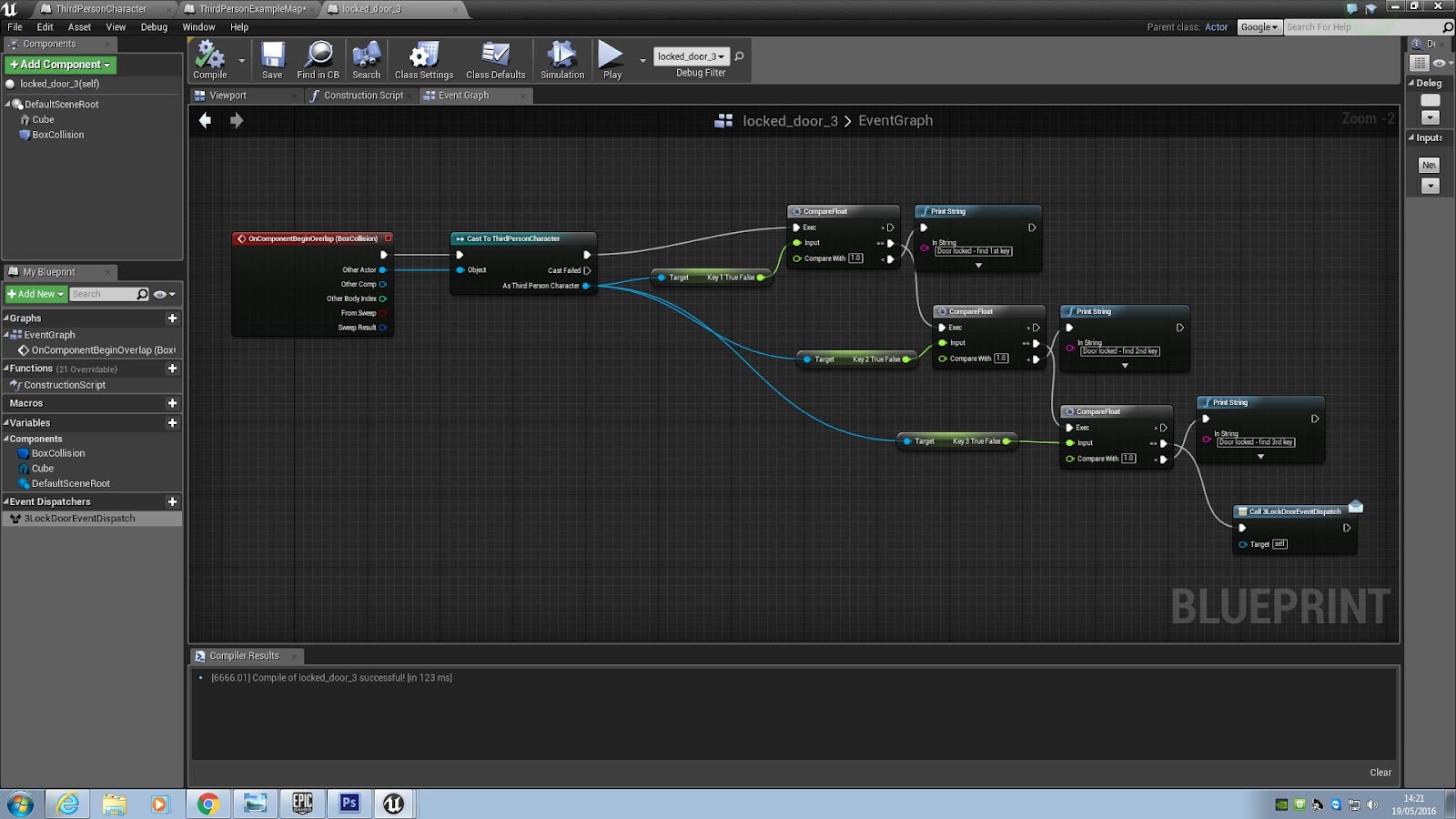
This is the logic flow that determines whether or not that the player has all the keys collected and whether the door will open. The red event node on the left is called ‘OnEventBeginOverlap’ and refers to the door actor. We need to reference exactly what should be triggering the script upon colliding with the door, which is of course the third person character. We have already set up 3 variables within the player character blueprint that determine whether the player has picked the keys ups. These are ‘Key 1 True False’, ‘Key 2 True False’, and ‘Key 3 True False’. Initially set to false, each variable becomes set to true when the player collects the relevant key actor. The logic above works it’s way through comparing each of these variables with 1 - true. If any variable still equals 0, false, the logic for triggering the opening of the door cannot complete. Instead a message prints informing the player they still have to collect that key.
If the logic reaches the end and all key collection variables are set to true, the event dispatcher to trigger the opening of the door is called. The matinee to open the door is inside the level blueprint. All matinees are triggered from here, as they are unique to the level. Level blueprints and normal blueprints have to have special logic to talk to each other as they quite different entities. That is where event dispatchers come in - they are essentially telling the game code “listen out for this command - when you hear it, carry out the actions specified by the event dispatcher message”. We have named our event dispatcher ‘3LockDoorEventDispatch’.
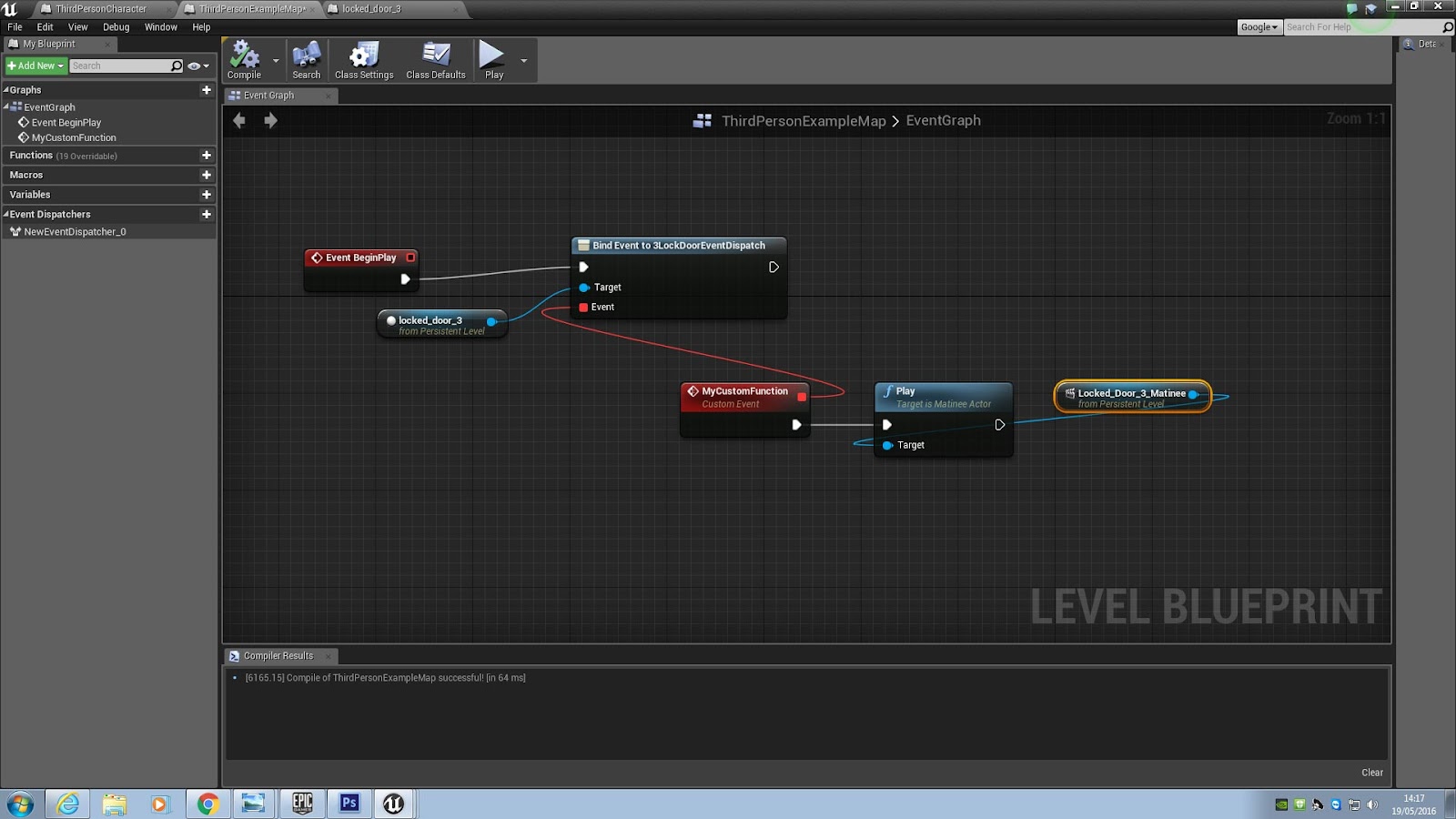
Over in the level blueprint, the code will always be ‘listening out’ for the event dispatch command. The red node ‘Event BeginPlay’ tells the logic to start being aware of the event dispatcher the moment the game starts to play. We tell the computer what actions to do by binding them to the phrase ‘3LockDoorEventDispatch’. After that we target the actor that will trigger the dispatch which is the door, Following that we tell the computer to finally play the matinee of the sliding door that we created. The animation should then trigger and the door will slide open.
Making an explosion
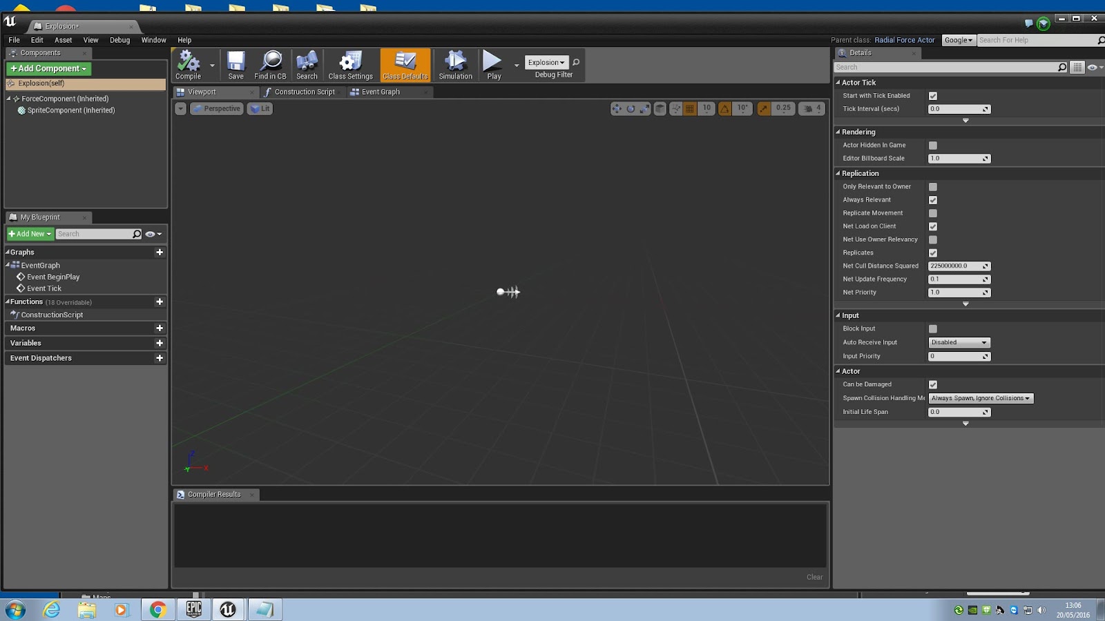
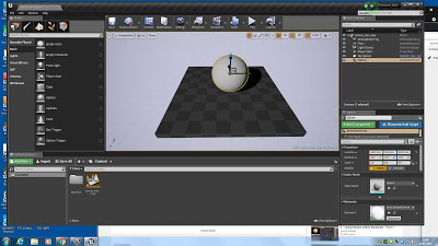
This is a typical example of how an actor is created. For our grenade actor, we want a specially created explosion that carries its own unique properties. We can set up the blueprint to swap with the grenade actor when the grenade strikes something. The illusion will be of the grenade exploding in a huge burst of flame. Every actor’s creation begins with a small white orb to denote the centre of the object. This is shown below.
~
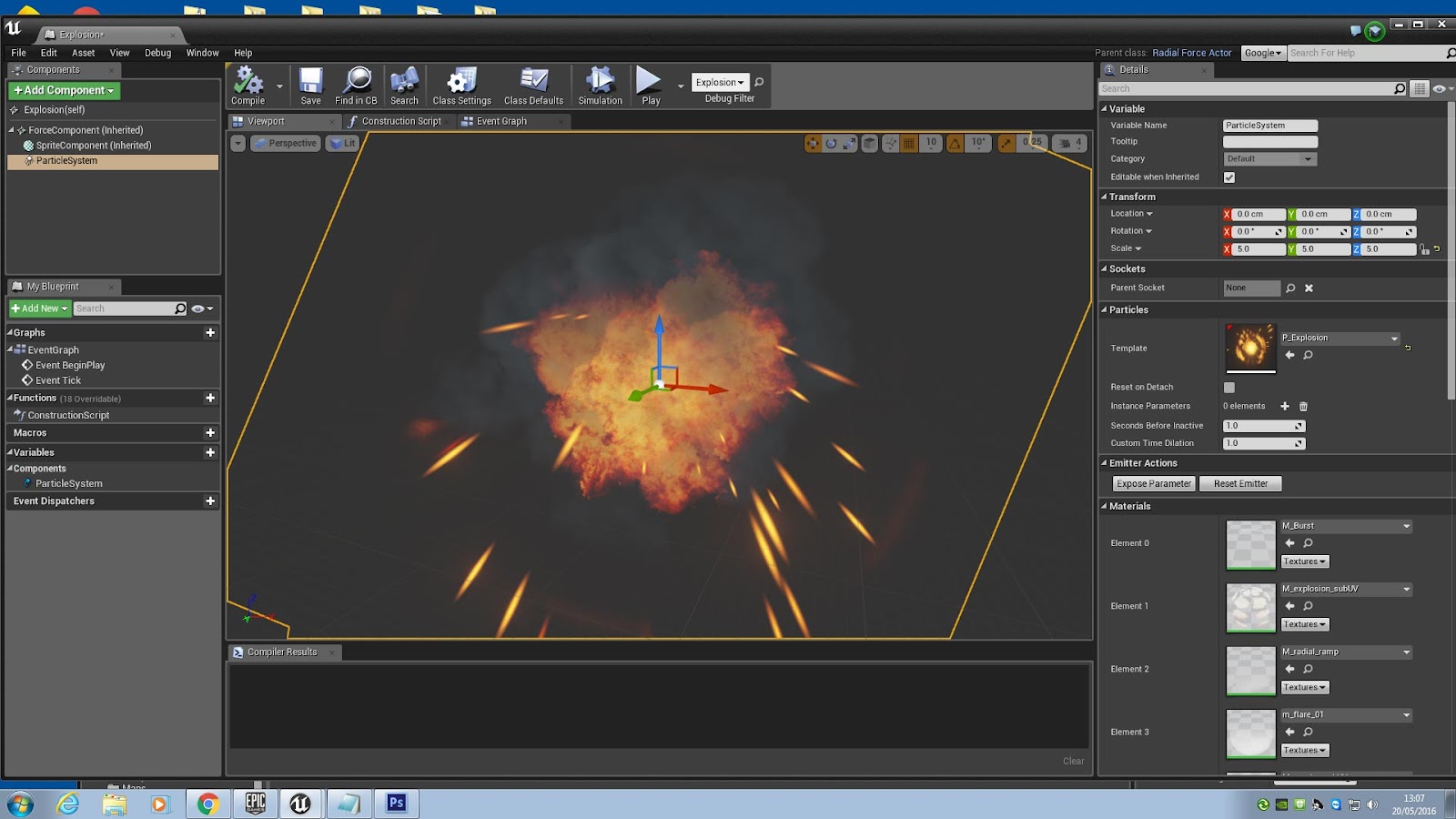
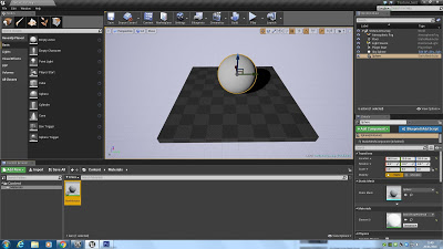
Creating a component in a blueprint is a simple task. By clicking the 'Add Component' button and selecting from a menu we can add all manner of behaviours and properties to our actor. These can range from tasks such as importing a mesh from Maya or adding rules for velocity and speed through to creating collision rules or particle effects.
In the case of our explosion, there are only a few simple components we need to add. The first is the particle effect 'P_Explosion' that comes with Unreal as standard. Using the X,Y and Z coordinates we can alter the size of the explosion as well as its overall intensity.
Additionally we can specify the blast radius and the force with which it will propel any objects around it outwards - this is known as a ‘force component’, which we shall be setting up to fire in the next step.
We can also set up a collision box component that will help to identify which objects to destroy that. Any actors that overlap the explosion collision box can be set to be destroyed upon detonation.
One of the most helpful things about components is that by selecting one and clicking one of the green boxes on the right of the screen we can quickly assign individual behaviours to just that component and not the whole actor. For example, with our zombies we have set up a collision begin overlap box for both a grenade and a fireball. With two different collision boxes we can set up two completely different kind of behaviour, even though they both have the same command 'begin overlap'. In the case of our game, we can set fireball to chip away at an enemy's damage or have a grenade take it all and kill the enemy instantly.
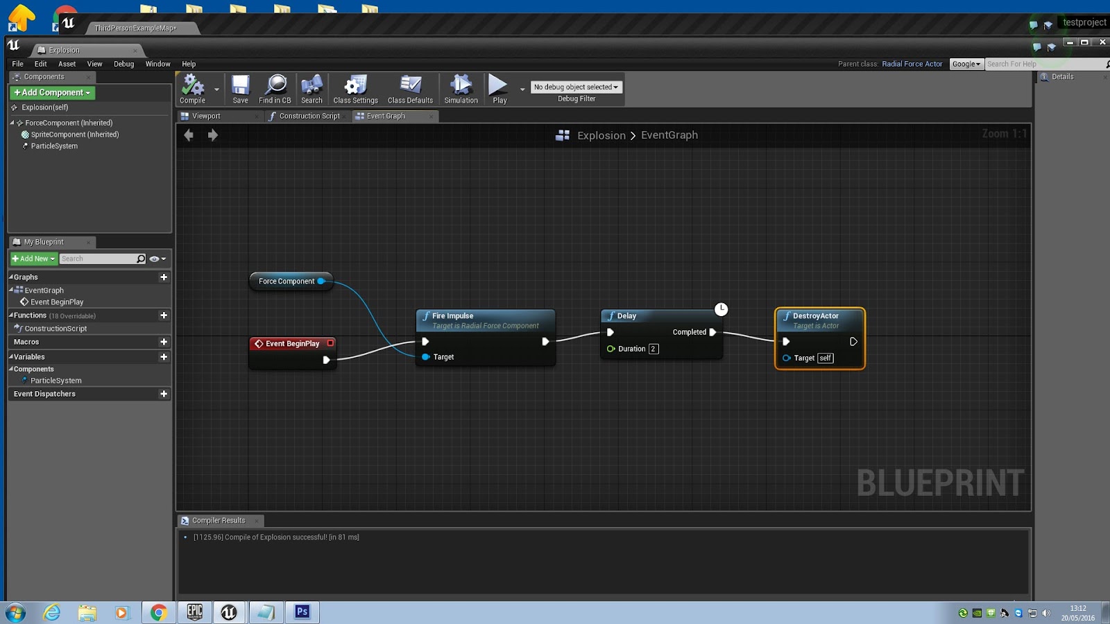
This is a short blueprint that we set up inside the event graph of the blueprint actor. The red node ‘Event BeginPlay’ will trigger whenever the actor is first introduced into the game. If you remember, we specified the grenade actor to swap for an explosion actor on impact, creating the illusion of an explosion. The first thing we want to do in the above blueprint is trigger the effect of an explosion - this is called an ‘impulse’. The impulse needs to refer to the specifics that we set up in the force component, so we set that up as the impulse target. Following this we have a short delay of two seconds so we can play a short burst of the ‘P_Explosion’ animation. After this we destroy the explosion actor, removing it from the game world entirely using the ‘Destroy Actor’ node. If we called ‘Destroy Actor’ before the delay, the explosion would disappear without us seeing any animation. Therefore, the order we call these nodes in is vital to achieving the effect we want to get.
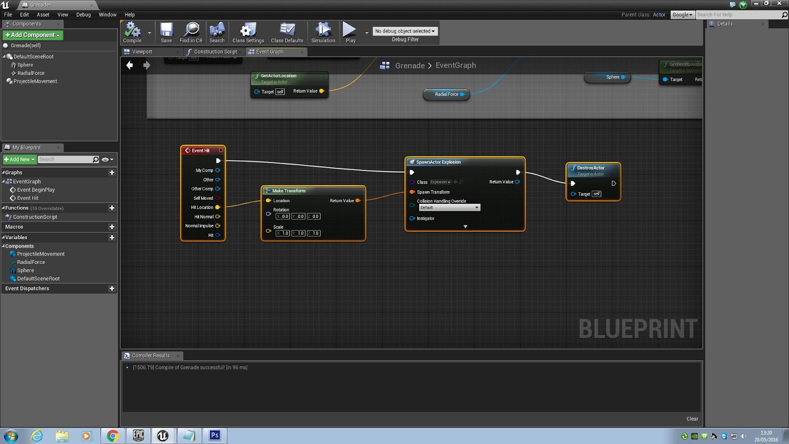
The above is a short logic sequence determining how the grenade should swap for the explosion upon striking something. We use ‘Event Hit’. To place the explosion at the right point in the landscape, we use the ‘Make Transform’ node, which will make the explosion actor appear at the hit location.
Creating a material in Unreal
A material is basically a coloured paint that you can apply to an object in Unreal. We need to tackle Blueprint material editors, which can at first seem confusing. However, understanding what each value means makes life simpler from the outset. So, here is what each refers to in the editor node:
- Base Colour - Your colour, chosen from a colour picker. RGB value.
- Metallic - (Set to 0 or 1) - 0 is metallic, 1 is non metallic.
- Specular - How shiny a surface is - THIS WILL ONLY WORK ON NON METALLIC SURFACES
- Roughness - (Set to 0.1 to 0.9) - How much the light is bounced around from a surface and how cleanly - e.g, imagine how shiny a ball of glass is compared to a ball of chalk)
- Emissive - How much the material glows
- Normals - Lumps and bumps, identified by a separate bump map texture.
Colours are termed as floating point colours. To simplify this imagine a pixel. A pixel is made up of:
- R
- G
- B
- A (Alpha) - transparency 0 (0 = 0% transparent) - 1 (1.0 = 100% fully opaque)
Some other terms I refer to:
- Constant - Hold 1 and LMB
- Constant 3 Vector (Simple RGB Colour) - Hold 3 and LMB
With an understanding of these terms, we can go about making a material colour that we can apply to an object:
In the Content Browser, we create a new folder called 'Materials'
In the materials folder, right click in the Content Browser. Choose 'New Material'. Name it appropriately. Double click the material to open it in the Blueprint editor.
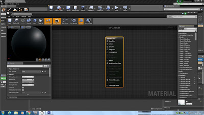
Here's that editor node! All the terms are above in this post, so consult those if you're not sure. For a simple material, we'll only need to use a few of them.

Hold 3 and left click in a space. The Constant 3 Vector field should appear.

Double click it and choose a colour. Drag a connecting wire from the white pin to the Base Colour pin.

Next, metallic setting. Hold 1 and left click in a space. The constants field should appear.
Set it to 0 or 1 in the value filed under Material Expression Constant on the left. Drag off the white pin and connect it to the Metallic pin.

Next roughness. Hold 1 and left click in a space. The constants field should appear.
Set it to 0.1 or 0.9 in the value filed under Material Expression Constant on the left. Drag off the white pin and connect it to the Roughness pin.
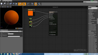
Next Specular. Hold 1 and left click in a space. The constants field should appear.
Set it to 0 or 1 in the value filed under Material Expression Constant on the left. Drag off the white pin and connect it to the Specular pin.
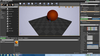
Click save and then click go back to the Unreal editor viewport. Choose your object then just drag your newly created colour onto it to change it's colour.